Asus N3150I-C User Guide - Page 11
Motherboard layout, Layout contents, Connectors/Jumpers/Slots/LED - quad core
 |
View all Asus N3150I-C manuals
Add to My Manuals
Save this manual to your list of manuals |
Page 11 highlights
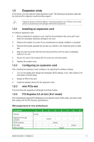
1.2.3 Motherboard layout 1 2 3 45 6 17.0cm(6.7in) KBMS CPU_FAN CHA_FAN LAN_USBE12 ATX12V LANGuard USB3_12 USBE34 USB3_34 19 ASM 1442K Intel® SOC HDMI BATTERY 18 17 16 COM1 VGA AAFP BZ1 COM2 TPM AUDIO1 RTL 8111H CLCMOS ALC 887 64Mb BIOS Super I/O LPT PANEL_SW CHASSIS PCIEX4 LVDS LCD_BLKT_PANEL VCC_PWR_SEL BLKT_PWR_SEL F_PANEL 15 14 13 12 11 10 9 8 1.2.4 Layout contents Connectors/Jumpers/Slots/LED 1. USB 2.0 connector (10-pin USBE34) 2. CPU and chassis fan connectors (4-pin CPU_FAN, 4-pin CHA_FAN) 3. USB 3.0 connector (20-1 pin USB3_34) 4. N3150I-C: Intel® Celeron Quad-core Processor N3150 N3050I-C: Intel® Celeron Dual-core Processor N3050 5. ATX power connectors (24-pin EATXPWR, 4-pin ATX12V) 6. DDR3 U-DIMM sockets 7. Serial ATA 6.0Gb/s connectors (7-pin SATA6G_1, SATA6G_2) 8. Display panel VCC power selector (3-pin VCC_PWR_SEL) 9. System panel connector (10-1 pin F_PANEL) 10. Display panel backlight power selector (3-pin BLKT_PWR_SEL) 11. Flat panel display brightness (8-pin LCD_BLKT_PANEL) 12. LVDS connector (40-pin LVDS) 13. Chassis intrusion connector (4-1 pin CHASSIS) 14. Display panel power connector (2-pin PANEL_SW) 15. LPT connector (26-1 pin LPT) 16. Clear RTC RAM (2-pin CLCMOS) 17. Front panel audio connector (10-1 pin AAFP) 18. Serial port connector (10-1 pin COM2) 19. TPM connector (14-1 pin TPM) ASUS N3150I-C / N3050I-C Mini PCIe SATA6G_1 SATA6G_2 N3150I-C N3050I-C DDR3_DIMM_A1 (64bit, 240-pin module) DDR3_DIMM_B1 (64bit, 240-pin module) EATX_PWR 17.0cm(6.7in) 5 7 Page 1-14 1-12 1-14 1-4 1-13 1-4 1-15 1-8 1-15 1-9 1-16 1-16 1-9 1-16 1-17 1-8 1-11 1-12 1-13 1-3
-
 1
1 -
2
-
3
-
4
-
5
-
 6
6 -
 7
7 -
 8
8 -
 9
9 -
 10
10 -
 11
11 -
 12
12 -
 13
13 -
 14
14 -
 15
15 -
 16
16 -
17
-
18
-
19
-
20
-
21
-
22
-
23
-
24
-
25
-
26
-
27
-
28
-
29
-
30
-
31
-
32
-
33
-
34
-
35
-
36
-
37
-
38
-
39
-
40
-
41
-
42
-
43
-
44
-
45
-
46
-
47
-
48
-
49
-
50
-
51
-
52
-
53
-
54
-
55
-
56
-
57
-
58
-
59
-
60
-
61
-
62
-
63
-
64
-
65
-
66
 |
 |
