Asus NCCH-DR NCCH-DR User Manual English Version - Page 26
of the support plates.
 |
View all Asus NCCH-DR manuals
Add to My Manuals
Save this manual to your list of manuals |
Page 26 highlights
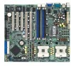
The support plates appear as shown when installed. 9. Install the motherboard with the external I/O ports toward the chassis rear panel. The CPU sockets should be right on top of the support plates. Heatsink hole matched to a nut on the support plate Make sure that the CPU heatsink holes on the motherboard perfectly match the metal nuts on the support plates; otherwise, you can not install the CPU heatsinks properly. 10. Secure the motherboard with 9 screws. Refer to section "2.2.2 Screw holes" for illustration. 2-6 Chapter 2: Hardware information
-
 1
1 -
2
-
3
-
4
-
5
-
6
-
7
-
8
-
9
-
10
-
11
-
12
-
13
-
14
-
15
-
16
-
17
-
18
-
19
-
20
-
 21
21 -
 22
22 -
 23
23 -
 24
24 -
 25
25 -
 26
26 -
 27
27 -
 28
28 -
 29
29 -
 30
30 -
 31
31 -
32
-
33
-
34
-
35
-
36
-
37
-
38
-
39
-
40
-
41
-
42
-
43
-
44
-
45
-
46
-
47
-
48
-
49
-
50
-
51
-
52
-
53
-
54
-
55
-
56
-
57
-
58
-
59
-
60
-
61
-
62
-
63
-
64
-
65
-
66
-
67
-
68
-
69
-
70
-
71
-
72
-
73
-
74
-
75
-
76
-
77
-
78
-
79
-
80
-
81
-
82
-
83
-
84
-
85
-
86
-
87
-
88
-
89
-
90
-
91
-
92
-
93
-
94
-
95
-
96
-
97
-
98
-
99
-
100
-
101
-
102
-
103
-
104
-
105
-
106
-
107
-
108
-
109
-
110
 |
 |

2-6
2-6
2-6
2-6
2-6
Chapter 2: Hardware information
Chapter 2: Hardware information
Chapter 2: Hardware information
Chapter 2: Hardware information
Chapter 2: Hardware information
9.
Install the motherboard with the
external I/O ports toward the
chassis rear panel. The CPU
sockets should be right on top
of the support plates.
10.
Secure the motherboard with 9 screws. Refer to section
“
2.2.2 Screw
holes
”
for illustration.
The support plates appear as
shown when installed.
Make sure that the CPU heatsink holes on the motherboard perfectly
match the metal nuts on the support plates; otherwise, you can not
install the CPU heatsinks properly.
Heatsink hole matched to
Heatsink hole matched to
Heatsink hole matched to
Heatsink hole matched to
Heatsink hole matched to
a nut on the support plate
a nut on the support plate
a nut on the support plate
a nut on the support plate
a nut on the support plate