Asus NCT-D NCT-D MB User Manual English Version
Asus NCT-D Manual
 |
View all Asus NCT-D manuals
Add to My Manuals
Save this manual to your list of manuals |
Asus NCT-D manual content summary:
- Asus NCT-D | NCT-D MB User Manual English Version - Page 1
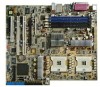
NCT-D (A) Motherboard - Asus NCT-D | NCT-D MB User Manual English Version - Page 2
Rights Reserved. No part of this manual, including the products COMPUTER INC. ("ASUS"). Product warranty or service will not ASUS HAS BEEN ADVISED OF THE POSSIBILITY OF SUCH DAMAGES ARISING FROM ANY DEFECT OR ERROR IN THIS MANUAL OR PRODUCT. SPECIFICATIONS AND INFORMATION CONTAINED IN THIS MANUAL - Asus NCT-D | NCT-D MB User Manual English Version - Page 3
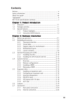
direction 2-2 2.2.2 Screw holes 2-2 2.2.3 Support plates for motherboard 2-3 2.2.4 Motherboard layout 2-7 2.2.5 Layout contents 2-8 2.3 Central Processing Unit (CPU 2-10 2.3.1 Installling the CPU 2-10 2.3.2 Installing the CPU heatsink and fan 2-12 2.4 System memory 2-14 2.4.1 Overview 2-14 - Asus NCT-D | NCT-D MB User Manual English Version - Page 4
BIOS 2 utility 4-5 4.1.4 ASUS EZ Flash utility 4-7 4.1.5 ASUS Update utility 4-8 4.2 BIOS setup program 4-11 4.2.1 BIOS menu screen 4-12 4.2.2 Menu bar 4-12 4.2.3 Navigation keys 4-12 4.2.4 Menu items 4-13 4.2.5 Sub-menu items 4-13 4.2.6 Configuration fields 4-13 4.2.7 Pop-up window - Asus NCT-D | NCT-D MB User Manual English Version - Page 5
4-24 4.4.9 PCI PnP 4-25 4.5 Power menu 4-27 4.5.1 Suspend Mode 4-27 4.5.2 Repost Video on S3 Resume 4-27 4.5.3 ACPI 2.0 Support 4-27 4.5.4 ACPI APIC Support 4-27 4.5.5 APM Configuration 4-28 4.5.6 Hardware Monitor 4-30 4.6 Boot menu 4-32 4.6.1 Boot Device Priority 4-32 4.6.2 Boot Settings - Asus NCT-D | NCT-D MB User Manual English Version - Page 6
for a Class B digital device, pursuant to Part 15 of the FCC Rules. These limits are and used in accordance with manufacturer's instructions, may cause harmful interference to radio for connection of the monitor to the graphics card is required to assure compliance with FCC regulations. - Asus NCT-D | NCT-D MB User Manual English Version - Page 7
signal cables from the motherboard, ensure that all service technician or your retailer. Operation safety • Before installing the motherboard and adding devices on it, carefully read all the manuals screws, and staples away from connectors, slots, sockets and circuitry. • Avoid dust, humidity, and - Asus NCT-D | NCT-D MB User Manual English Version - Page 8
you need when installing and configuring the motherboard. How this guide is organized This manual contains the following parts: • Chapter 1: Product introduction This chapter describes the features of the motherboard and the new technology it supports. • Chapter 2: Hardware information This chapter - Asus NCT-D | NCT-D MB User Manual English Version - Page 9
following symbols used throughout this manual. D A N G E R / W A R N I N G : Information to prevent injury to yourself when trying to complete a task. C A U T I O N : Information to prevent damage to the components when trying to complete a task. I M P O R T A N T : Instructions that you MUST follow - Asus NCT-D | NCT-D MB User Manual English Version - Page 10
specifications summary CPU Chipset Front Side Bus Memory Expansion slots Storage Wi-Fi solution (optional) Audio LAN USB IEEE 1394 Dual 604-pin sockets for Intel® Xeon™ processors with Extended Memory 64-bit Technology (EM64T) Supports Intel® Hyper-Threading Technology Northbridge : Intel® E7525 - Asus NCT-D | NCT-D MB User Manual English Version - Page 11
NCT-D (A) specifications summary Special features BIOS features Rear panel Internal connectors Power Requirement Form Factor Support CD contents ASUS Post Reporter™ ASUS Q-Fan2 ASUS EZ Flash ASUS CrashFree BIOS 2 ASUS MyLogo2 ASUS Instant Music AMI BIOS, 8 MB Flash ROM, Green, PnP, DMI2.0a, SMBIOS - Asus NCT-D | NCT-D MB User Manual English Version - Page 12
xii - Asus NCT-D | NCT-D MB User Manual English Version - Page 13
This chapter describes the motherboard features and the new technologies it supports. 1Product introduction - Asus NCT-D | NCT-D MB User Manual English Version - Page 14
Chapter summary 1 1.1 Welcome 1-1 1.2 Package contents 1-1 1.3 Special features 1-2 ASUS NCT-D - Asus NCT-D | NCT-D MB User Manual English Version - Page 15
C D s ASUS motherboard support CD (includes ASWM) D o c u m e n t a t i o n User guide O p t i o n a l i t e m s ASUS WiFi-g card (PCI) with dipolar antenna ASUS WiFi-b card (Wi-Fi slot) with dipolar antenna If any of the above items is damaged or missing, contact your retailer. ASUS NCT-D 1-1 - Asus NCT-D | NCT-D MB User Manual English Version - Page 16
enables support for 64-bit operating systems, such as 64-bit Windows® and Linux. See page 2-10 for details. Intel® E7525 and Intel® 6300 ESB chipset The Intel® E7525 Memory Controller Hub (MCH) and the Intel® 6300ESB I/O controller hub (ICH) provide the vital interfaces for the motherboard. The - Asus NCT-D | NCT-D MB User Manual English Version - Page 17
to Gigabit bandwidth. The motherboard also comes with the ASUS proprietary Wi-Fi slot that supports an optional WiFi-b/g card for your wireless Internet, any. See page 2-25 for details. S/PDIF digital sound ready The motherboard supports the S/PDIF Out function through the S/PDIF interfaces on the - Asus NCT-D | NCT-D MB User Manual English Version - Page 18
31 for details. USB 2.0 technology The motherboard implements the Universal Serial Bus (USB) 2.0 specification, dramatically increasing the connection speed from ASUS features CrashFree BIOS 2 This feature allows you to restore the original BIOS data from the support CD in case when the BIOS codes - Asus NCT-D | NCT-D MB User Manual English Version - Page 19
details. ASUS MyLogo2™ This new feature present in the motherboard allows you ASUS EZ Flash BIOS With the ASUS EZ Flash, you can easily update the system BIOS even before loading the operating system. No need to use a DOS-based utility or boot from a floppy disk. See page 4-7 for details. ASUS NCT - Asus NCT-D | NCT-D MB User Manual English Version - Page 20
1-6 Chapter 1: Product introduction - Asus NCT-D | NCT-D MB User Manual English Version - Page 21
This chapter lists the hardware setup procedures that you have to perform when installing system components. It includes description of the jumpers and connectors on the motherboard. 2 Hardware information - Asus NCT-D | NCT-D MB User Manual English Version - Page 22
Chapter summary 2 2.1 Before you proceed 2-1 2.2 Motherboard overview 2-2 2.3 Central Processing Unit (CPU 2-10 2.4 System memory 2-14 2.5 Expansion slots 2-16 2.6 Jumpers 2-19 2.7 Connectors 2-24 ASUS NCT-D - Asus NCT-D | NCT-D MB User Manual English Version - Page 23
motherboard components or change any motherboard settings. • Unplug the power cord from the wall socket the motherboard, peripherals, and/or components. Onboard LED The motherboard comes motherboard component. The illustration below shows the location of the onboard LED. SB_PWR1 NCT-D NCT-D Standby - Asus NCT-D | NCT-D MB User Manual English Version - Page 24
in the correct orientation. The edge with external ports goes to the rear part of the chassis as indicated in the image below. 2.2.2 Screw holes Place ten (10) screws into the holes indicated by circles to secure the motherboard to the chassis. Do not overtighten the screws! Doing so can damage the - Asus NCT-D | NCT-D MB User Manual English Version - Page 25
breakage due to the weight of the CPU heatsinks, your motherboard package comes with a solution kit that consists of: • 2 x metal support plates • 1 x contour sheet • 3 different sets of metal nuts and rubber pads nut size that is slightly lower than the standoffs on your chassis. ASUS NCT-D 2-3 - Asus NCT-D | NCT-D MB User Manual English Version - Page 26
4. Use a plier to attach four nuts to the bolts on the metal support plate. 5. Align a rubber pad to the rectagular mark on the center of the plate, then press to attach. 6. Remove the adhesive label underneath a plate. 2-4 Chapter 2: Hardware information - Asus NCT-D | NCT-D MB User Manual English Version - Page 27
Carefully align and place the plate on a rectangular cut on the contour sheet. Make sure that the metal support plates fit perfectly to the rectangular cuts on the contour sheet; otherwise, the CPU heatsink screws would not align to the metal nuts. 8. Repeat steps 4 and 7 to prepare and install the - Asus NCT-D | NCT-D MB User Manual English Version - Page 28
I/O ports toward the chassis rear panel. The CPU sockets should be right on top of the support plates. Heatsink hole matched to a nut on the support plate Make sure that the CPU heatsink holes on the motherboard perfectly match the metal nuts on the support plates; otherwise, you can not install the - Asus NCT-D | NCT-D MB User Manual English Version - Page 29
12in) 2.2.4 Motherboard layout PS/2KBMS Intel E7525 MCH CPU2 REAR_FAN2 CPU_FAN2 FP_AUDIO1 Broadcom BCM5751 J4 FM_CPU2 J3 SEC_IDE AD1980 LAN_EN1 CD1 AUX1 SUPER I/O BUZZER1 GAME1 AMI BIOS TSB43AB22A WIFI NCT-D IE1394_2 1394_EN1 USB_EN1 CR2032 3V Lithium Cell CMOS Power Intel 6300ESB ICH - Asus NCT-D | NCT-D MB User Manual English Version - Page 30
2.2.5 Layout contents Slots 1. CPU sockets 2. DDR2 DIMM sockets 3. PCI/PCI-X/PCI Express slots 4. Wi-Fi slot Jumpers 1. Clear RTC RAM (CLRTC1) 2. CPU fan pin selection (3-pin FM_CPU1, FM_CPU2) 3. USB device wake-up (3-pin USBPW12, USBPW34) 5. Keyboard power (3-pin KBPWR1) 6. IEEE 1394 controller - Asus NCT-D | NCT-D MB User Manual English Version - Page 31
Chassis intrusion connector (4-1 pin CHASSIS1) 8. Front panel audio connector (10-1 pin FP_AUDIO1) 9. CPU, Chassis, and Power Fan connectors (3-pin CPU_FAN1/2, REAR_FAN1/2, FRNT_FAN1/2) 10. IEEE 1394a port connector 30 2-30 2-31 2-31 2-32 2-33 2-33 2-34 2-34 2-34 2-35 2-35 2-35 2-35 ASUS NCT-D 2-9 - Asus NCT-D | NCT-D MB User Manual English Version - Page 32
™ processor supports 800 MHz system bus and Extended Memory 64-bit Technology (EM64T). 2.3.1 Installling the CPU To install a CPU: 1. Locate the CPU sockets on the motherboard. Intel Xeon Gold Arrow NCT-D NCT-D Socket 604 If installing only one CPU, use the socket CPU1. 2. Flip up the socket lever - Asus NCT-D | NCT-D MB User Manual English Version - Page 33
CPU. The lever clicks on the side tab to indicate that it is locked. 6. Apply the thermal interface material (thermal grease) to the top of the CPU. This thermal grease should come with the CPU package. 7. Repeat steps 1 to 6 if you wish to install a second CPU. Marked corner (gold arrow) ASUS NCT - Asus NCT-D | NCT-D MB User Manual English Version - Page 34
to ensure optimum thermal condition and performance. When you buy a boxed Intel® CPU, the package includes the heatsink, fan, retention brackets, screws, thermal grease, installation manual, and other items that are necessary for CPU installation. • Make sure that you have applied the thermal grease - Asus NCT-D | NCT-D MB User Manual English Version - Page 35
to the 4-pin connector labeled CPU_FAN1. Do not forget to connect the CPU fan connector! Hardware monitoring errors may occur if you fail to plug this a second CPU, then connect the fan cable to the 4-pin connector labeled CPU_FAN2. The heatsinks appear as shown when installed. ASUS NCT-D 2-13 - Asus NCT-D | NCT-D MB User Manual English Version - Page 36
sockets. • Always install DIMMs with the same CAS latency. For optimum compatibility, it is recommended that you obtain memory modules from the same vendor. Refer to the DDR2 Qualified Vendors List on the ASUS website (www.asus.com) for details. • This motherboard does not support memory modules - Asus NCT-D | NCT-D MB User Manual English Version - Page 37
. 1. Simultaneously press the retaining clips outward to unlock the DIMM. Support the DIMM lightly with your fingers when pressing the retaining clips. The DIMM might get damaged when it 1 flips out with extra force. 2. Remove the DIMM from the socket. 2 1 DDR2 DIMM notch ASUS NCT-D 2-15 - Asus NCT-D | NCT-D MB User Manual English Version - Page 38
. See Chapter 4 for information on BIOS setup. 2. Assign an IRQ to the card. Refer to the tables on the next page. 3. Install the software drivers for the expansion card. When using PCI cards on shared slots, ensure that the drivers support "Share IRQ" or that the cards do not need IRQ assignments - Asus NCT-D | NCT-D MB User Manual English Version - Page 39
PCI steering* PS/2 Compatible Mouse Port* Numeric Data Processor Primary IDE Channel Secondary IDE Channel * These IRQs are usually available for ISA or PCI devices. ASUS NCT-D 2-17 - Asus NCT-D | NCT-D MB User Manual English Version - Page 40
/PCI-X slots support cards such as a LAN card, SCSI card, USB card, and other cards that comply with PCI 2.3 and PCI-X 1.0a specifications. The figure shows a LAN card installed on a PCI slot. 2.5.5 PCI Express™ x8/x16 slots This motherboard supports PCI Express™ x16 graphic cards that comply with - Asus NCT-D | NCT-D MB User Manual English Version - Page 41
-D NCT-D Clear RTC RAM CLRTC1 2 1 Normal (Default) 3 2 Clear CMOS You do not need to clear the RTC when the system hangs due to overclocking. For system failure due to overclocking, use the C.P.R. (CPU Parameter Recall) feature. Shut down and reboot the system so the BIOS can automatically reset - Asus NCT-D | NCT-D MB User Manual English Version - Page 42
the connected USB devices. Set to +5VSB to wake up from S3 and S4 sleep modes (no power to CPU, DRAM in slow refresh, power supply in reduced power mode). NCT-D NCT-D USB device wake up USBPW12 12 23 Enable Disable (Default) USBPW34 2 1 Enable 3 2 Disable (Default) • The USB device wake-up - Asus NCT-D | NCT-D MB User Manual English Version - Page 43
the +5VSB lead, and a corresponding setting in the BIOS. KBPWR1 2 1 Enable (Default) 3 2 Disable NCT-D NCT-D Keyboard power setting 5 . IEEE 1394 controller setting (3- activate the 1394 feature. NCT-D NCT-D 1394 Function setting 1394_EN1 2 1 Enable (Default) 3 2 Disable ASUS NCT-D 2-21 - Asus NCT-D | NCT-D MB User Manual English Version - Page 44
allow you to enable or disable the onboard Broadcom BCM5751 Gigabit LAN controller. Set to pins 1-2 to activate the Gigabit LAN feature. NCT-D NCT-D LAN_EN setting LAN_EN1 21 32 Enable (Default) Disable 7 . SATA controller setting (3-pin SATA_EN1) These jumpers allow you to enable or disable - Asus NCT-D | NCT-D MB User Manual English Version - Page 45
8 . USB controller setting (3-pin USB_EN1) These jumpers allow you to enable or disable the onboard VIA VT6212 PCI USB 2.0 controller. Set to pins 1-2 to activate the USB feature. NCT-D NCT-D USB setting USB_EN1 2 1 Enable (Default) 3 2 Disable ASUS NCT-D 2-23 - Asus NCT-D | NCT-D MB User Manual English Version - Page 46
Mbps connection 1 Gbps connection ACT/LINK SPEED LED LED LAN port 5 . L i n e I n p o r t ( l i g h t b l u e ) . This port connects a tape, CD, DVD player, or other audio sources. 6 . L i n e O u t p o r t ( l i m e ) . This port connects a headphone or a speaker. In 4-channel, 6-channel, and - Asus NCT-D | NCT-D MB User Manual English Version - Page 47
for pointing devices or other serial devices. 1 1 . C o a x i a l S / P D I F O u t p o r t . This port connects an external audio output device via a coaxial S/PDIF cable. 1 2 . P S / 2 k e y b o a r d p o r t ( p u r p l e ) . This port is for a PS/2 keyboard. ASUS NCT-D 2-25 - Asus NCT-D | NCT-D MB User Manual English Version - Page 48
-D NCT-D Floppy disk drive connector 2 . Primary IDE connector (40-1 pin PRI_IDE, SEC_IDE) This connector is for an Ultra DMA 100/66 signal cable. The Ultra DMA 100/66 signal cable has three connectors: a blue connector for the primary IDE connector on the motherboard, a black connector for an Ultra - Asus NCT-D | NCT-D MB User Manual English Version - Page 49
embedded in the Intel® 6300ESB chip. NCT-D NCT-D SATA connectors SATA1 SATA2 GND RSATA_TXP1 RSATA_TXN1 GND RSATA_RXN1 RSATA_RXP1 GND GND RSATA_TXP2 RSATA_TXN2 GND RSATA_RXN2 RSATA_RXP2 GND Important notes on Serial ATA • You must install Windows® 2000 Service Pack 4 or the Windows® XP Service - Asus NCT-D | NCT-D MB User Manual English Version - Page 50
for Serial ATA signal cables. These connectors support up to four Serial ATA hard disk drives ; otherwise, you cannot enter the RAID utility and SATA BIOS setup during POST. 5 . Hard disk activity LED connector NCT-D NCT-D SCSI/SATA card activity LED connector 2-28 Chapter 2: Hardware information - Asus NCT-D | NCT-D MB User Manual English Version - Page 51
allow you to receive stereo audio input from sound sources such as CD-ROM. TV tuner, or MPEG card. CD1 (Black) AUX1 (White) NCT-D NCT-D Internal audio connectors 7 . Chassis intrusion feature. CHASSIS1 GND Chassis Signal (Default) +5VSB_MB NCT-D NCT-D Chassis intrusion connector ASUS NCT-D 2-29 - Asus NCT-D | NCT-D MB User Manual English Version - Page 52
supports AC'97 audio specifications. FP_AUDIO1 MIC2 MICPWR Line out_R NC Line out_L AGND +5VA BLINE_OUT_R BLINE_OUT_L NCT-D NCT-D Front panel audio connector 9 . CPU . Insufficient air flow inside the system may damage the motherboard components. These are not jumpers! Do not place jumper - Asus NCT-D | NCT-D MB User Manual English Version - Page 53
the system chassis. These USB connectors comply with USB 2.0 specification that supports up to 480 Mbps connection speed. USB+5V USB_P6USB_P6+ NCT-D NCT-D USB 2.0 connectors USB78 1 USB56 1 Never connect a 1 3 9 4 c a b l e to the USB connectors. Doing so will damage the motherboard! ASUS NCT - Asus NCT-D | NCT-D MB User Manual English Version - Page 54
until the connectors completely fit. • Use of an SSI 12 V Specification 2.0-compliant power supply unit (PSU) that provides a minimum power of Ground Ground Ground -5 Volts +5 Volts +5 Volts +5 Volts Ground NCT-D NCT-D SSI Power connectors For Power Supply with 20-pin Power Connector 2-32 - Asus NCT-D | NCT-D MB User Manual English Version - Page 55
then install the module to a slot opening at the back of the system chassis. COM2 PIN 1 NCT-D NCT-D Serial port connector 14. GAME/MIDI port connector (16-1 pin GAME1) This connector is for a J1B2 J1CY GND GND J1CX J1B1 +5V NCT-D NCT-D Game connector GAME1 MIDI_IN J2B2 J2CY MIDI_OUT J2CX J2B1 +5V - Asus NCT-D | NCT-D MB User Manual English Version - Page 56
PANEL1) This connector supports several chassis-mounted functions. Power LED Speaker PLED+ NC PLEDMLED+ MLEDNC +5V GND GND SPKO PANEL1 HDLED+ GND NC GND PWRBTN GND NC RESET GND NCT-D NCT-D System panel connector IDELED PWRSW Reset The sytem panel connector is color-coded for easy connection - Asus NCT-D | NCT-D MB User Manual English Version - Page 57
chassis-mounted system warning speaker. The speaker allows you to hear system beeps and warnings. • ATX power button/soft-off button (Yellow 2-pin on or puts the system in sleep or soft-off mode depending on the BIOS settings. Pressing the power switch for more than four seconds while the system - Asus NCT-D | NCT-D MB User Manual English Version - Page 58
2-36 Chapter 2: Hardware information - Asus NCT-D | NCT-D MB User Manual English Version - Page 59
This chapter describes the power up Powerin3g up sequence, the vocal POST messages, and ways of shutting down the system. - Asus NCT-D | NCT-D MB User Manual English Version - Page 60
Chapter summary 3 3.1 Starting up for the first time 3-1 3.2 Powering off the computer 3-2 3.3 ASUS POST Reporter 3-3 ASUS NCT-D - Asus NCT-D | NCT-D MB User Manual English Version - Page 61
continuous beeps followed by four short beeps Error Keyboard controller error Refresh Time error No master drive detected Floppy controller failure Hardware component failure 7. At power on, hold down the key to enter the BIOS Setup. Follow the instructions in Chapter 4. ASUS NCT-D 3-1 - Asus NCT-D | NCT-D MB User Manual English Version - Page 62
u r n O f f button to shut down the computer. 3. The power supply should turn off after Windows® shuts down. 3.2.2 Using the dual function power switch While the system is ON, pressing the power switch for -off mode, depending on the BIOS setting. Pressing the power switch for more than four seconds - Asus NCT-D | NCT-D MB User Manual English Version - Page 63
memory" for instructions on installing a DIMM. • Install a PCI graphics card into one of the PCI slots, or a PCI Express AGP card into the PCI Express x16 slot. • Make sure that your graphics card is not defective. • Check your CPU overclocking settings in the BIOS setup and restore the default CPU - Asus NCT-D | NCT-D MB User Manual English Version - Page 64
system. • Make sure that your CPU fan supports the fan speed detection function. • Check your power supply and make sure it is not defective. • Call ASUS technical support for assistance. See the "ASUS contact information" on the inside front cover of this user guide. • No action required You can - Asus NCT-D | NCT-D MB User Manual English Version - Page 65
application from the support CD. To avoid conflicts, do not run the Winbond Voice Editor while running the ASUS PC Probe application. Launching the Voice Editor You can launch the program from the Windows® desktop by click the Play button. The default language setting is English. ASUS NCT-D 3-5 - Asus NCT-D | NCT-D MB User Manual English Version - Page 66
event messages for the language you selected appear on the Voice Editor main window. Not all events on some languages have a corresponding message due to file Voice Editor main window to update the EEPROM. 4. Click Y e s to confirm. The next time you boot your computer, the ASUS Post Reporter - Asus NCT-D | NCT-D MB User Manual English Version - Page 67
POST messages if your language is not supported or if you wish to to replace message for each event. 3. Use a recording software (e.g. Windows® Recorder) to record your messages, then save the messages d W a v e F i l e window. 5. Copy the wave files that you recorded to the database, then close the - Asus NCT-D | NCT-D MB User Manual English Version - Page 68
name with an . f l h extension, then click Save. 12. Click the W r i t e button to compress the file and copy into the EEPROM. 13. Click Y e s on the confirmation window that appears. If you receive an error message telling you that the files exceed the total allowable size, do any or all of the - Asus NCT-D | NCT-D MB User Manual English Version - Page 69
This chapter tells how to change the system settings through the BIOS Setup menus. Detailed descriptions of the BIOS parameters are also provided. 4 BIOS setup - Asus NCT-D | NCT-D MB User Manual English Version - Page 70
Chapter summary 4 4.1 Managing and updating your BIOS 4-1 4.2 BIOS setup program 4-11 4.3 Main menu 4-14 4.4 Advanced menu 4-18 4.5 Power menu 4-27 4.6 Boot menu 4-32 4.7 Exit menu 4-37 ASUS NCT-D - Asus NCT-D | NCT-D MB User Manual English Version - Page 71
a bootable floppy disk or the motherboard support CD when the BIOS file fails or gets corrupted.) 3. A S U S E Z F l a s h (Updates the BIOS in DOS mode using a floppy disk or the motherboard support CD.) 4. A S U S U p d a t e (Updates the BIOS in Windows® environment.) Refer to the corresponding - Asus NCT-D | NCT-D MB User Manual English Version - Page 72
the Windows® 2000 CD to the optical drive. c. Click S t a r t, then select R u n. d. In the O p e n field, type D:\bootdisk\makeboot a: assuming that D is your optical drive letter. e. Press , then follow screen instructions to continue. 2. Copy the original or the latest motherboard BIOS - Asus NCT-D | NCT-D MB User Manual English Version - Page 73
(www.asus.com) and download the latest BIOS file for the motherboard. Save the BIOS file to a bootable floppy disk. Write the BIOS filename on a piece of paper. You need to type the exact BIOS filename at the DOS prompt. 2. Copy the AFUDOS utility (afudos.exe) from the motherboard support CD to the - Asus NCT-D | NCT-D MB User Manual English Version - Page 74
system boot failure! 5. The utility returns to the DOS prompt after the BIOS update process is completed. Reboot the system from the hard disk drive. A:\>afudos /iNCTD.ROM /pbnc AMI Firmware Update Utility - Version 1.19(ASUS V2.07(03.11.24BB)) Copyright (C) 2002 American Megatrends, Inc. All rights - Asus NCT-D | NCT-D MB User Manual English Version - Page 75
2 utility The ASUS CrashFree BIOS 2 is an auto recovery tool that allows you to restore the BIOS file when it fails or gets corrupted during the updating process. You can update a corrupted BIOS file using the motherboard support CD or the floppy disk that contains the updated BIOS file. • Prepare - Asus NCT-D | NCT-D MB User Manual English Version - Page 76
updating the BIOS! Doing so can cause system boot failure! 4. Restart the system after the utility completes the updating process. The recovered BIOS may not be the latest BIOS version for this motherboard. Visit the ASUS website (www.asus.com) to download the latest BIOS file. 4-6 Chapter 4: BIOS - Asus NCT-D | NCT-D MB User Manual English Version - Page 77
+ during the Power-On Self Tests (POST). To update the BIOS using EZ Flash: 1. Visit the ASUS website (www.asus.com) to download the latest BIOS file for the motherboard and rename the same to N C T D . R O M. 2. Save the BIOS file to a floppy disk, then restart the system. 3. Press - Asus NCT-D | NCT-D MB User Manual English Version - Page 78
BIOS file • Download the latest BIOS file from the Internet • Update the BIOS from an updated BIOS file • Update the BIOS directly from the Internet, and • View the BIOS version information. This utility is available in the support CD that comes with the motherboard package. ASUS Update requires - Asus NCT-D | NCT-D MB User Manual English Version - Page 79
Updating the BIOS through the Internet To update the BIOS through the Internet: 1. Launch the ASUS Update utility from the Windows® desktop by clicking S t a r t > P r o g r a m s > A S U S > A S U S U p d a t e > A S U S U p d a t e. The ASUS Update main window appears. 2. Select U p d a t e B I O - Asus NCT-D | NCT-D MB User Manual English Version - Page 80
to download. Click Next. 5. Follow the screen instructions to complete the update process. The ASUS Update utility is capable of updating itself through the Internet. Always update the utility to avail all its features. Updating the BIOS through a BIOS file To update the BIOS through a BIOS file - Asus NCT-D | NCT-D MB User Manual English Version - Page 81
under the Exit Menu. See section "4.7 Exit Menu." • The BIOS setup screens shown in this section are for reference purposes only, and may not exactly match what you see on your screen. • Visit the ASUS website (www.asus.com) to download the latest BIOS file for this motherboard. ASUS NCT-D 4-11 - Asus NCT-D | NCT-D MB User Manual English Version - Page 82
Fourth IDE Slave IDE Configuration System Information [11:51:19] [Thu 05/07/2004] [1.44M, 3.5 in] : [ST320413A] : [ASUS CD-S520/A] : [Not Detected] : [Not Detected] : [Not Detected] : [Not Detected] Use [ENTER], [TAB] or [SHIFT keys differ from one screen to another. 4-12 Chapter 4: BIOS setup - Asus NCT-D | NCT-D MB User Manual English Version - Page 83
the menu bar displays the specific items for that menu. For 19] [Thu 05/07/2004] [1.44M, 3.5 in] : [ST320413A] : [ASUS CD-S520/A : [Not Detected] : [Not Detected] : [Not Detected] : [Not . Configure DRAM Timing by SPD Memory Acceleration Mode DRAM Idle Timer DRAm window Scroll bar ASUS NCT-D 4-13 - Asus NCT-D | NCT-D MB User Manual English Version - Page 84
an overview of the basic system information. Refer to section "4.2.1 BIOS menu screen" for information on the menu screen items and how Information [11:51:19] [Thu 05/07/2004] [1.44M, 3.5 in] : [ST320413A] : [ASUS CD-S520/A] : [Not Detected] : [Not Detected] : [Not Detected] : [Not Detected] Use - Asus NCT-D | NCT-D MB User Manual English Version - Page 85
the type of IDE drive. Setting to [Auto] allows automatic selection of the appropriate IDE device type. Select [CDROM] if you are specifically configuring a CD-ROM drive. Select [ARMD] (ATAPI Removable Media Device) if your device is either a ZIP, LS-120, or MO drive. Configuration options: [Not - Asus NCT-D | NCT-D MB User Manual English Version - Page 86
Set to [Enhanced Mode] if you are using native OS including Windows® 2000/XP. Configuration options: [Compatible Mode] [Enhanced Mode] Enhanced Mode Support On [S-ATA] Allows you to use native OS on Serial ATA connectors as RAID sets. Configuration options: [No] [Yes] 4-16 Chapter 4: BIOS setup - Asus NCT-D | NCT-D MB User Manual English Version - Page 87
problems, Memory Size : 512MB AMI BIOS Displays the auto-detected BIOS information Processor Displays the auto-detected CPU specification System Memory Displays the auto-detected system memory Select Screen Select Item +- Change Option F1 General Help F10 Save and Exit ESC Exit ASUS NCT - Asus NCT-D | NCT-D MB User Manual English Version - Page 88
MPS Configuration CPU Configuration Chipset Onboard you to enable or disable the Instant Music feature in BIOS. Configuration options: [Disabled] [Enabled] Enabling Instant Music 29 for details. Instant Music CD-ROM Drive [IDE Secondary Master] Allows you to select the CD-ROM drive that you wish to - Asus NCT-D | NCT-D MB User Manual English Version - Page 89
Speech POST Reporter [Enabled] Allows you to enable or disable the ASUS Speech POST Reporter™ feature. Configuration options: [Disabled] [Enabled] Configuration PCI Express Configuration Onboard LAN [Auto] Auto: Visible if card Enable: Always visible Disable: Always hide Onboard LAN [Auto] - Asus NCT-D | NCT-D MB User Manual English Version - Page 90
the USB controller legacy mode is enabled. If no USB device is detected, the legacy USB support is disabled. Configuration options: [Disabled] [Enabled] [Auto] USB 2.0 Controller [Enabled] Allows Mbps) or FullSpeed (12 Mbps). Configuration options: [HiSpeed ] [FullSpeed ] 4-20 Chapter 4: BIOS setup - Asus NCT-D | NCT-D MB User Manual English Version - Page 91
Bus frequency. The BIOS auto-detects the default value of this item. Use the < + > or < - > keys to adjust the values. Configuration options: [ 8]...[28] You can only adjust the R a t i o C M O S settings if you installed an unlocked CPU. Refer to the CPU documentation for details. ASUS NCT-D 4-21 - Asus NCT-D | NCT-D MB User Manual English Version - Page 92
Disabled] Setting this item to [Enabled] allows legacy operating systems to boot even without support for CPUs with extended CPUID functions. Configuration options: [Disabled] [Enabled] 4.4.7 Chipset The onboard LAN controller. Configuration options: [Disabled] [Enabled] 4-22 Chapter 4: BIOS setup - Asus NCT-D | NCT-D MB User Manual English Version - Page 93
Memory Remap Feature DDR2 400 [Enabled] ENABLE: Allow remapping of overlapped PCI memory above the total physical memory. DISABLE: Do not allow remapping of memory Memory Remap Feature [Enabled] Allows you to remap the overlap PCI memory over the total physical memory allows the BIOS to auto-detect - Asus NCT-D | NCT-D MB User Manual English Version - Page 94
IO Chipset Serial Port1 Address Serial Port2 Address Parallel Port Address Onboard Game/MIDI Port [3F8/IRQ4] [2F8/IRQ3] [378] [Disabled] Allows BIOS to Select Serial Port1 Base Addresses. Serial Port1 Address [3F8/IRQ4] Allows you to select the Serial Port1 base address. Configuration options - Asus NCT-D | NCT-D MB User Manual English Version - Page 95
for either PCI/PnP or legacy ISA devices, and setting the memory size block for legacy ISA devices. Take caution when changing the [Yes], BIOS assigns an IRQ to PCI VGA card if the card requests for an IRQ. When set to [No], BIOS does not assign an IRQ to the PCI VGA card even if ASUS NCT-D 4-25 - Asus NCT-D | NCT-D MB User Manual English Version - Page 96
card, when required. Configuration options: [Auto] [PCI Slot1] [PCI Slot2] [PCI Slot3] [PCI Slot4] [PCI Slot5] [PCI Slot6] IRQ-xx assigned to [PCI Device] When set to [PCI Device], the specific 3 DMA Channel 5 DMA Channel 6 DMA Channel 7 Reserved Memory Size [PCI Device] [PCI Device] [PCI Device] [ - Asus NCT-D | NCT-D MB User Manual English Version - Page 97
] Allows you to enable or disable the Advanced Configuration and Power Interface (ACPI) support in the Application-Specific Integrated Circuit (ASIC). When set to Enabled, the ACPI APIC table pointer is included in the RSDT pointer list. Configuration options: [Disabled] [Enabled] ASUS NCT-D 4-27 - Asus NCT-D | NCT-D MB User Manual English Version - Page 98
Disabled] Enable or disable APM. Power Management [Enabled] Allows you to enable or disable the motherboard Advance Power Management (APM) feature. Configuration options: [Enabled] [Disabled] Video Power Down Mode is pressed. Configuration options: [On/Off] [Suspend] 4-28 Chapter 4: BIOS setup - Asus NCT-D | NCT-D MB User Manual English Version - Page 99
State] Power On By PS/2 Keyboard [Disabled] Allows you to use specific keys on the keyboard to turn on the system. This feature requires an allows you to turn on the system through a PCI LAN or modem card. This feature requires an ATX power supply that provides at least 1A on ASUS NCT-D 4-29 - Asus NCT-D | NCT-D MB User Manual English Version - Page 100
motherboard and CPU CPU, front, and rear fan speed in rotations per minute (RPM). If the fan is not connected to the motherboard , the field shows N/A. Smart Fan Control [Disabled] Allows you to enable or disable the ASUS Allows you to set the CPU and system threshold temperature before the - Asus NCT-D | NCT-D MB User Manual English Version - Page 101
Voltage, 3.3V Voltage, 5V Voltage, 5VSB Voltage, VBAT Voltage, 12V Voltage The onboard hardware monitor automatically detects the voltage output through the onboard voltage regulators. ASUS NCT-D 4-31 - Asus NCT-D | NCT-D MB User Manual English Version - Page 102
Device 2nd Boot Device 3rd Boot Device 4th Boot Device [1st FLOPPY DRIVE] [PM-ST330620A] [PS-ASUS CD-S360] [MBA v7.5.12 Slot 0] Specifies the boot sequence from the available devices. A device enclosed in the system. Configuration options: [xxxxx Drive] [Disabled] 4-32 Chapter 4: BIOS setup - Asus NCT-D | NCT-D MB User Manual English Version - Page 103
feature. Configuration options: [Disabled] [Enabled] Set this item to [Enabled] to use the ASUS MyLogo2™ feature. Add On ROM Display Mode [Force BIOS] Sets the display mode for option ROM. Configuration options: [Force BIOS] [Keep Current] Bootup Num-Lock [On] Allows you to select the power-on state - Asus NCT-D | NCT-D MB User Manual English Version - Page 104
of at least six letters and/or numbers, then press . 3. Confirm the password when prompted. The message "Password Installed" appears after you successfully set your password. To change the supervisor password, follow the same steps as in setting a user password. 4-34 Chapter 4: BIOS setup - Asus NCT-D | NCT-D MB User Manual English Version - Page 105
press . The message "Password Uninstalled" appears. If you forget your BIOS password, you can clear clear it by erasing the CMOS Real Time Clock (RTC) RAM. See section "2.6 Jumpers" for information on how to erase the RTC RAM. After you have set a supervisor password, the other items appear - Asus NCT-D | NCT-D MB User Manual English Version - Page 106
steps as in setting a user password. Clear User Password Select this item to clear the user password. Password Check [Setup] When set to [Setup], BIOS checks for user password when accessing the Setup utility. When set to [Always], BIOS checks for user password both when accessing Setup and booting - Asus NCT-D | NCT-D MB User Manual English Version - Page 107
, the BIOS asks for a confirmation before exiting. Discard Changes Allows you to discard the selections you made and restore the previously saved values. After selecting this option, a confirmation appears. Select Y e s to discard any changes and load the previously saved values. ASUS NCT-D 4-37 - Asus NCT-D | NCT-D MB User Manual English Version - Page 108
to load the default values for each of the parameters on the Setup menus. When you select this option or if you press , a confirmation window appears. Select Y e s to load default values. Select E x i t & S a v e C h a n g e s or make other changes before saving the values to the non-volatile - Asus NCT-D | NCT-D MB User Manual English Version - Page 109
This chapter describes the power up Reference informaAtion sequence, the vocal POST messages, and ways of shutting down the system. - Asus NCT-D | NCT-D MB User Manual English Version - Page 110
Appendix summary A A.1 NCT-D block diagram A-1 ASUS NCT-D - Asus NCT-D | NCT-D MB User Manual English Version - Page 111
A.1 NCT-D block diagram Intel XeonTM Processor with 800MHz system bus System Bus 64bit, 800 MHz Intel XeonTM Processor with 800MHz system bus Intel E7525 MCH Four DDRII400 4xDDR 400 DIMM slots ( -A Keyboard Serial Port EEPROM System information Floppy Mouse BIOS Flash 8 Mbit ASUS NCT-D A-1 - Asus NCT-D | NCT-D MB User Manual English Version - Page 112
A-2 Appendix A: Reference information
-
 1
1 -
 2
2 -
 3
3 -
 4
4 -
 5
5 -
 6
6 -
 7
7 -
8
-
9
-
10
-
11
-
12
-
13
-
14
-
15
-
16
-
17
-
18
-
19
-
20
-
21
-
22
-
23
-
24
-
25
-
26
-
27
-
28
-
29
-
30
-
31
-
32
-
33
-
34
-
35
-
36
-
37
-
38
-
39
-
40
-
41
-
42
-
43
-
44
-
45
-
46
-
47
-
48
-
49
-
50
-
51
-
52
-
53
-
54
-
55
-
56
-
57
-
58
-
59
-
60
-
61
-
62
-
63
-
64
-
65
-
66
-
67
-
68
-
69
-
70
-
71
-
72
-
73
-
74
-
75
-
76
-
77
-
78
-
79
-
80
-
81
-
82
-
83
-
84
-
85
-
86
-
87
-
88
-
89
-
90
-
91
-
92
-
93
-
94
-
95
-
96
-
97
-
98
-
99
-
100
-
101
-
102
-
103
-
104
-
105
-
106
-
107
-
108
-
109
-
110
-
111
-
112
 |
 |

Motherboard
NCT-D (A)