Asus NCT-D NCT-D MB User Manual English Version - Page 56
System power LED Green 3-pin PLED
 |
View all Asus NCT-D manuals
Add to My Manuals
Save this manual to your list of manuals |
Page 56 highlights
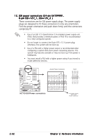
15. Backplane SMBus connector (6-1 pin BPSMB1) This connector allows you to connect SMBus (System Management Bus) devices. Devices communicate with an SMBus host and/or other SMBus devices using the SMBus interface. FAN_PWM I2C_2_CLK# GND I2C_2_DATA# +5V NCT-D NCT-D SMBus connector BPSMB1 1 16. System panel connector (20-pin PANEL1) This connector supports several chassis-mounted functions. Power LED Speaker PLED+ NC PLEDMLED+ MLEDNC +5V GND GND SPKO PANEL1 HDLED+ GND NC GND PWRBTN GND NC RESET GND NCT-D NCT-D System panel connector IDELED PWRSW Reset The sytem panel connector is color-coded for easy connection. Refer to the connector descriptions on the next page for details. • System power LED (Green 3-pin PLED) This 3-pin connector is for the system power LED. Connect the chassis power LED cable to this connector. The system power LED lights up when you turn on the system power, and blinks when the system is in sleep mode. 2-34 Chapter 2: Hardware information
-
 1
1 -
2
-
3
-
4
-
5
-
6
-
7
-
8
-
9
-
10
-
11
-
12
-
13
-
14
-
15
-
16
-
17
-
18
-
19
-
20
-
21
-
22
-
23
-
24
-
25
-
26
-
27
-
28
-
29
-
30
-
31
-
32
-
33
-
34
-
35
-
36
-
37
-
38
-
39
-
40
-
41
-
42
-
43
-
44
-
45
-
46
-
47
-
48
-
49
-
50
-
 51
51 -
 52
52 -
 53
53 -
 54
54 -
 55
55 -
 56
56 -
 57
57 -
 58
58 -
 59
59 -
 60
60 -
 61
61 -
62
-
63
-
64
-
65
-
66
-
67
-
68
-
69
-
70
-
71
-
72
-
73
-
74
-
75
-
76
-
77
-
78
-
79
-
80
-
81
-
82
-
83
-
84
-
85
-
86
-
87
-
88
-
89
-
90
-
91
-
92
-
93
-
94
-
95
-
96
-
97
-
98
-
99
-
100
-
101
-
102
-
103
-
104
-
105
-
106
-
107
-
108
-
109
-
110
-
111
-
112
 |
 |
