Asus P I-AP55T P/I-AP55T User's manual - Page 33
Asus P I-AP55T Manual
 |
View all Asus P I-AP55T manuals
Add to My Manuals
Save this manual to your list of manuals |
Page 33 highlights
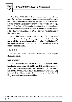
Upgrade Guide Updating the Flash BIOS This mainboard has two BIOS ROM chip options. It can use either of two programmable 'flash' EPROM chips, 5-volt or 12-volt, either of which you can update when BIOS upgrades are available. Jumper JP9 enables programming for the BIOS ROM chip. There are two settings. The default setting, which shorts pins 1&2, is for Write-Protect/Normal Read. The other setting, which shorts pins 2&3, is for Enable Programming. When you finish programming, always set JP9 back to the default Write-Protect/Normal Read setting. The following example illustrates this procedure. BIOS Update Procedure Set jumper for Programming Use FMW to update BIOS Set jumper back to Normal 1. Set JP9 to the Programming Enabled setting. 2. Refer to Chapter 3 for instructions on using the Flash Memory Writer Utility to install a new BIOS file in the flash chip. 3. When you have successfully installed the new BIOS, set JP9 back to the Write Protect/Normal setting to disable programming. 2-13
-
 1
1 -
2
-
3
-
4
-
5
-
6
-
7
-
8
-
9
-
10
-
11
-
12
-
13
-
14
-
15
-
16
-
17
-
18
-
19
-
20
-
21
-
22
-
23
-
24
-
25
-
26
-
27
-
 28
28 -
 29
29 -
 30
30 -
 31
31 -
 32
32 -
 33
33 -
 34
34 -
 35
35 -
 36
36 -
 37
37 -
 38
38 -
39
-
40
-
41
-
42
-
43
-
44
-
45
-
46
-
47
-
48
-
49
-
50
-
51
-
52
-
53
-
54
-
55
-
56
-
57
-
58
-
59
-
60
-
61
-
62
-
63
-
64
-
65
-
66
-
67
-
68
-
69
-
70
-
71
-
72
-
73
-
74
-
75
-
76
-
77
-
78
-
79
-
80
-
81
-
82
-
83
-
84
-
85
-
86
-
87
 |
 |
