Asus P2-P5N9300 User Manual - Page 13
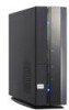
Front panel of P4-P5N9300, Hard disk drive HDD LED.
 |
View all Asus P2-P5N9300 manuals
Add to My Manuals
Save this manual to your list of manuals |
Page 13 highlights
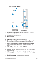
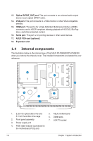
Front panel of P4-P5N9300 3 4 2 13 6 7 8 1 5 9 10 12 11 Front panel (close) Front panel (open) 1. Hard disk drive (HDD) LED. This LED lights up when data is read from or written to the hard disk drive. 2. Optical disk drive (ODD) bay cover. 3. Front panel cover. 4. Optical disk drive eject button. Press this button to eject an optical disk. 5. Power button. Press this button to turn the system on. 6. 3-in-1 card reader. This 3-in-1 card reader supports the MultiMediaCard, Secure Digital™ card, and Memory Stick™/Memory Stick PRO™ card. 7. USB 2.0 port 9. �T�h�i�s�U��n�i�v�e�r�s�a�l��S�e�r�i�a�l�B��u�s��2�.�0��(U��S�B���2�.�0�)�p�o��r�t �c�o�n�n��e�c�t�s��to� USB 2.0 devices such as a mouse, printer, scanner, camera, PDA, and others. 8. USB / eSATA port. �T�h�i�s�p��o�r�t�c�o�n��n�e�c�t�s��to��a��U��S�B���2�.0��d��e�v�i�c�e��o�r�a�n��e��x�te��rn��a�l Serial ATA hard disk drive. 9. 4-pin IEEE 1394 port. This port connects to an IEEE 1394 device such as a digital camrecorder. 10. USB 2.0 ports 10 and 11. These Universal Serial Bus 2.0 (USB 2.0) ports connect to USB 2.0 devices such as a mouse, printer, scanner, camera, PDA, and others. 11. Microphone port (pink). This port connects to a microphone. ASUS P2-P5N9300/P4-P5N9300 1-3
-
 1
1 -
2
-
3
-
4
-
5
-
6
-
7
-
 8
8 -
 9
9 -
 10
10 -
 11
11 -
 12
12 -
 13
13 -
 14
14 -
 15
15 -
 16
16 -
 17
17 -
 18
18 -
19
-
20
-
21
-
22
-
23
-
24
-
25
-
26
-
27
-
28
-
29
-
30
-
31
-
32
-
33
-
34
-
35
-
36
-
37
-
38
-
39
-
40
-
41
-
42
-
43
-
44
-
45
-
46
-
47
-
48
-
49
-
50
-
51
-
52
-
53
-
54
-
55
-
56
-
57
-
58
-
59
-
60
-
61
-
62
-
63
-
64
-
65
-
66
-
67
-
68
-
69
-
70
-
71
-
72
-
73
-
74
-
75
-
76
-
77
-
78
-
79
-
80
-
81
-
82
 |
 |
