Asus P2-P5N9300 User Manual - Page 14
Rear panel, This switch allows you to adjust the system input voltage
 |
View all Asus P2-P5N9300 manuals
Add to My Manuals
Save this manual to your list of manuals |
Page 14 highlights
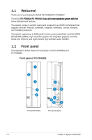
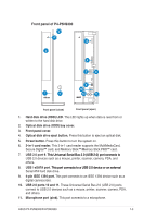
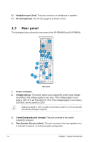
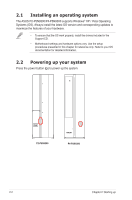
12. Headphone port (lime). This port connects to a headphone or speaker. 13. IR card (optional). This IR card supports a remote control. 1.3 Rear panel The illustration below shows the rear panel of the P2-P5N9300 and P4-P5N9300. 2 1 86 4 7 53 10 9 12 11 14 15 16 13 17 18 Rear panel 1. Power connector. 2. Voltage selector. This switch allows you to adjust the system input voltage according to the voltage supply in your area. If the voltage supply in your area is 100-127V, set this switch to 115V. If the voltage supply in your area is 200-240V, set this switch to 230V. Setting the switch to 115V in a 230V environment or 230V in a 115 environment will seriously damage the system! 3. Center/Subwoofer port (orange). This port connects to the center/ subwoofer speakers. 4. Rear Speaker Out port (black). This port connects to the rear speakers in a 4-channel, 6-channel, or 8-channel audio configuration. 1-4 Chapter 1: System introduction
-
 1
1 -
2
-
3
-
4
-
5
-
6
-
7
-
8
-
 9
9 -
 10
10 -
 11
11 -
 12
12 -
 13
13 -
 14
14 -
 15
15 -
 16
16 -
 17
17 -
 18
18 -
 19
19 -
20
-
21
-
22
-
23
-
24
-
25
-
26
-
27
-
28
-
29
-
30
-
31
-
32
-
33
-
34
-
35
-
36
-
37
-
38
-
39
-
40
-
41
-
42
-
43
-
44
-
45
-
46
-
47
-
48
-
49
-
50
-
51
-
52
-
53
-
54
-
55
-
56
-
57
-
58
-
59
-
60
-
61
-
62
-
63
-
64
-
65
-
66
-
67
-
68
-
69
-
70
-
71
-
72
-
73
-
74
-
75
-
76
-
77
-
78
-
79
-
80
-
81
-
82
 |
 |
