Asus P55SP4 P/I-P55SP4 User's manual - Page 47
PCl/PNP, Onboard, Setup
 |
View all Asus P55SP4 manuals
Add to My Manuals
Save this manual to your list of manuals |
Page 47 highlights
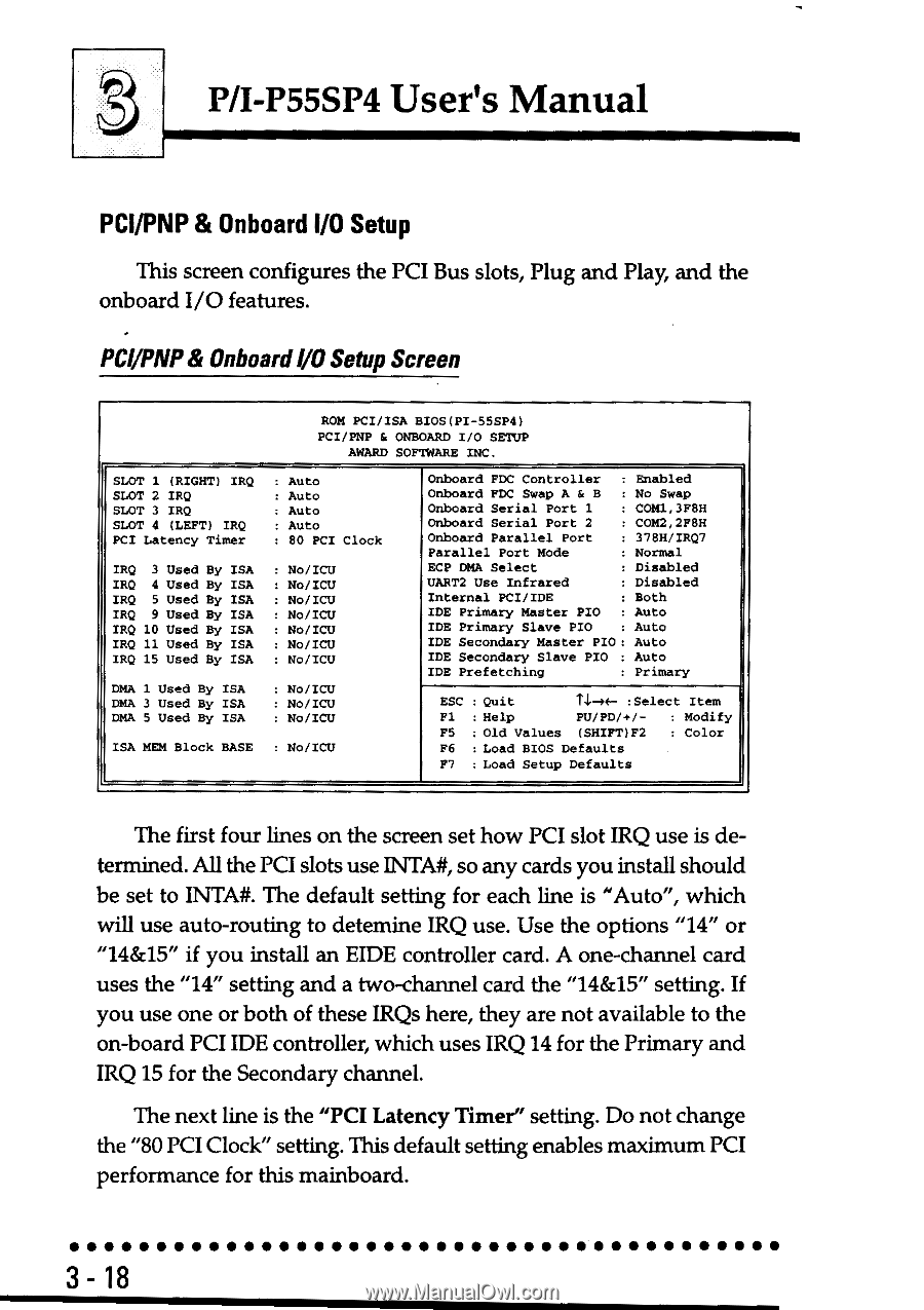
P/I-P55SP4 User's Manual PCl/PNP & Onboard I/O Setup This screen configures the PCI Bus slots, Plug and Play, and the onboard I/O features. PCl/PNP& OnboardI/O Setup Screen ROM PCI/ISA BIOS(PI-55SP6) PCI/PNP & ONBOARD I/O SETUP AWARD SOFTWARE INC. SLOT 1 (RIGHT) IRQ SLOT 2 IRQ SLOT 3 IRQ SLOT 4 (LEFT) IRQ PCI Latency Timer : Auto : Auto : Auto : Auto : 80 PCI Clock IRQ 3 Used By ISA IRQ 4 Used By ISA IRQ 5 Used By ISA IRQ 9 Used By ISA IRQ 10 Used By ISA IRQ 11 Used By ISA IRQ 15 Used By ISA : No/ICU : No/ICU : No/ICU : No/ICU : No/ICU : No/ICU : No/ICU DMA 1 Used By ISA DMA 3 Used By ISA DMA 5 Used By ISA : No/ICU : No/ICU : No/ICU ISA MEM Block BASE : No/ICU Onboard FDC Controller : Enabled Onboard FDC Swap A & B : No Swap Onboard Serial Port 1 COM1,3F8H Onboard Serial Port 2 : COM2,2F8H Onboard Parallel Port : 378H/IRQ7 Parallel Port Mode : Normal ECP DMA Select : Disabled UART2 Use Infrared : Disabled Internal PCI/IDE : Both IDE Primary Master PIO : Auto IDE Primary Slave PIO : Auto IDE Secondary Master PIO: Auto IDE Secondary Slave PIO : Auto IDE Prefetching : Primary ESC : Quit ti-n- :Select Item Fl : Help PU/PD/+/- : Modify F5 Old Values (SHIFT)F2 : Color P6 : Load BIOS Defaults F7 : Load Setup Defaults The first four lines on the screen set how PCI slot IRQ use is determined. All the PCI slots use INTA#, so any cards you install should be set to INTA#. The default setting for each line is "Auto", which will use auto-routing to detemine IRQ use. Use the options "14" or "14&15" if you install an EIDE controller card. A one-channel card uses the "14" setting and a two-channel card the "14&15" setting. If you use one or both of these IRQs here, they are not available to the on-board PCI IDE controller, which uses IRQ 14 for the Primary and IRQ 15 for the Secondary channel. The next line is the "PCI Latency Timer" setting. Do not change the "80 PCI Clock" setting. This default setting enables maximum PCI performance for this mainboard. 3-18
-
 1
1 -
2
-
3
-
4
-
5
-
6
-
7
-
8
-
9
-
10
-
11
-
12
-
13
-
14
-
15
-
16
-
17
-
18
-
19
-
20
-
21
-
22
-
23
-
24
-
25
-
26
-
27
-
28
-
29
-
30
-
31
-
32
-
33
-
34
-
35
-
36
-
37
-
38
-
39
-
40
-
41
-
 42
42 -
 43
43 -
 44
44 -
 45
45 -
 46
46 -
 47
47 -
 48
48 -
 49
49 -
 50
50 -
 51
51 -
 52
52 -
53
-
54
-
55
-
56
-
57
-
58
-
59
-
60
-
61
-
62
-
63
-
64
-
65
-
66
-
67
-
68
-
69
-
70
-
71
-
72
-
73
-
74
-
75
-
76
-
77
-
78
-
79
-
80
-
81
-
82
 |
 |