Asus P5SD2-X SE Motherboard Installation Guide - Page 40
P5SD2-X SE USB 2.0 Connectors
 |
View all Asus P5SD2-X SE manuals
Add to My Manuals
Save this manual to your list of manuals |
Page 40 highlights
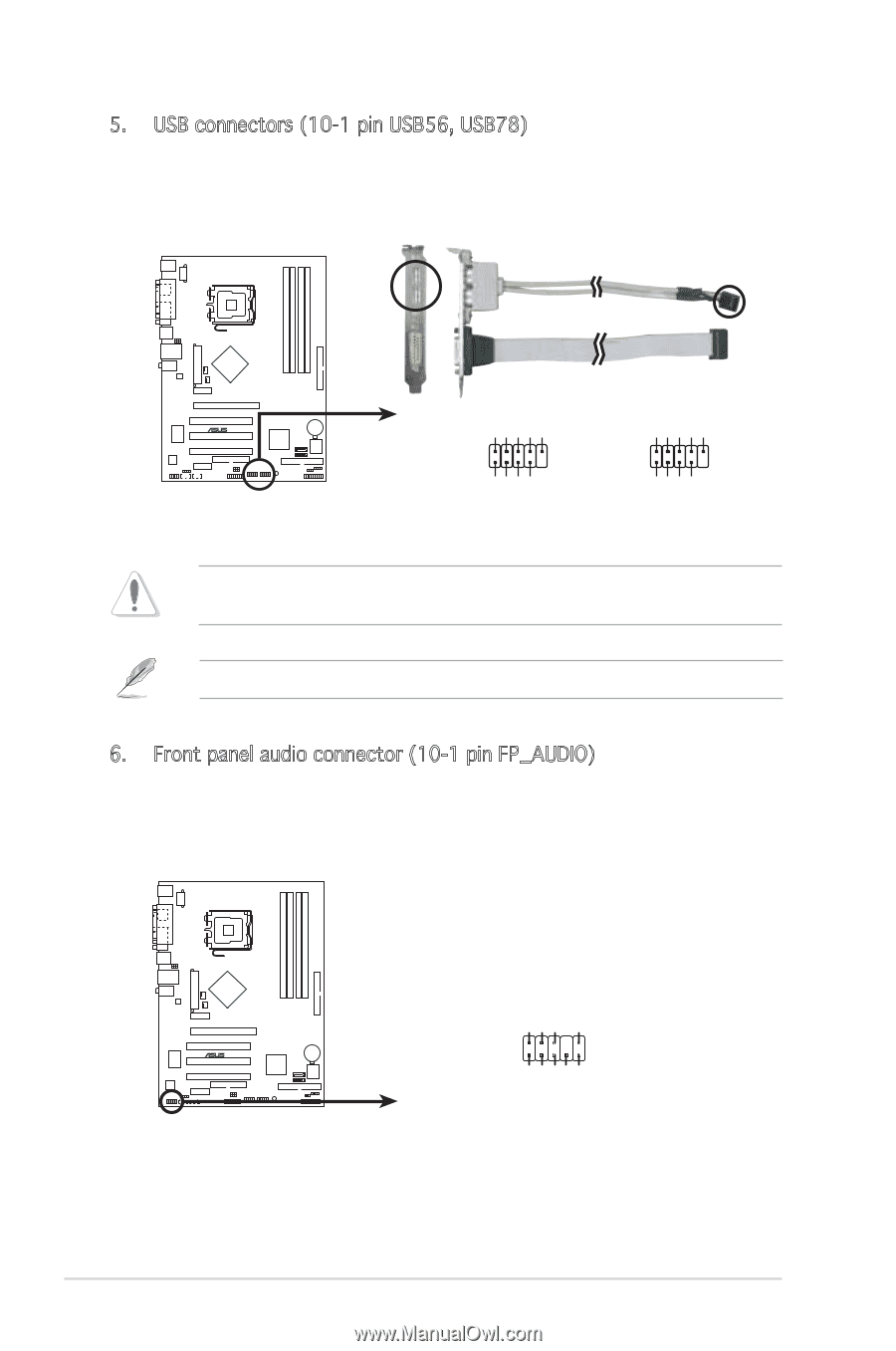
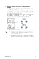
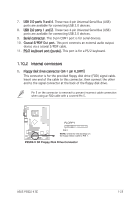
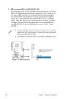
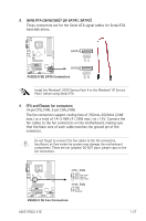
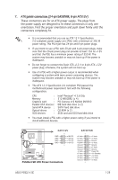
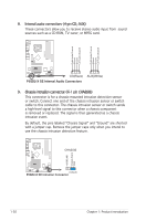
5. USB connectors (10-1 pin USB56, USB78) These connectors are for USB 2.0 ports. Connect the USB/GAME module cable to any of these connectors, then install the module to a slot opening at the back of the system chassis. P5SD2-X SE USB+5V USB_P8USB_P8+ GND NC USB+5V USB_P6USB_P6+ GND NC ® USB56 1 P5SD2-X SE USB 2.0 Connectors USB78 1 USB+5V USB_P7USB_P7+ GND USB+5V USB_P5USB_P5+ GND Never connect a 1394 cable to the USB connectors. Doing so will damage the motherboard! The GAME/MIDI module is purchased separately. 6. Front panel audio connector (10-1 pin FP_AUDIO) This connector is for a chassis-mounted front panel audio I/O module that supports legacy AC ʻ97 audio standard. Connect one end of the front panel audio I/O module cable to this connector. AGND +5VA BLINE_OUT_R BLINE_OUT_L P5SD2-X SE MIC2 MICPWR Line out_R NC Line out_L ® FP_AUDIO P5SD2-X SE Front Panel Audio Connector 1-28 Chapter 1: Product introduction
-
 1
1 -
2
-
3
-
4
-
5
-
6
-
7
-
8
-
9
-
10
-
11
-
12
-
13
-
14
-
15
-
16
-
17
-
18
-
19
-
20
-
21
-
22
-
23
-
24
-
25
-
26
-
27
-
28
-
29
-
30
-
31
-
32
-
33
-
34
-
 35
35 -
 36
36 -
 37
37 -
 38
38 -
 39
39 -
 40
40 -
 41
41 -
 42
42 -
 43
43 -
 44
44 -
 45
45 -
46
-
47
-
48
-
49
-
50
-
51
-
52
-
53
-
54
-
55
-
56
-
57
-
58
-
59
-
60
-
61
-
62
-
63
-
64
-
65
-
66
-
67
-
68
-
69
-
70
-
71
-
72
-
73
-
74
-
75
-
76
-
77
-
78
-
79
-
80
-
81
-
82
-
83
-
84
-
85
-
86
-
87
-
88
-
89
-
90
 |
 |