Asus P5VD1-X P5VD1-X User's Manual for English Edition
Asus P5VD1-X Manual
 |
View all Asus P5VD1-X manuals
Add to My Manuals
Save this manual to your list of manuals |
Asus P5VD1-X manual content summary:
- Asus P5VD1-X | P5VD1-X User's Manual for English Edition - Page 1
Motherboard P5VD1-X User Guide - Asus P5VD1-X | P5VD1-X User's Manual for English Edition - Page 2
OF BUSINESS, LOSS OF USE OR DATA, INTERRUPTION OF BUSINESS AND THE LIKE), EVEN IF ASUS HAS BEEN ADVISED OF THE POSSIBILITY OF SUCH DAMAGES ARISING FROM ANY DEFECT OR ERROR IN THIS MANUAL OR PRODUCT. SPECIFICATIONS AND INFORMATION CONTAINED IN THIS MANUAL ARE FURNISHED FOR INFORMATIONAL USE ONLY, AND - Asus P5VD1-X | P5VD1-X User's Manual for English Edition - Page 3
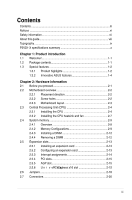
Memory Configurations 2-9 2.4.3 Installing a DIMM 2-12 2.4.4 Removing a DIMM 2-12 2.5 Expansion slots 2-13 2.5.1 Installing an expansion card 2-13 2.5.2 Configuring an expansion card 2-13 2.5.3 Interrupt assignments 2-14 2.5.4 PCI slots 2-15 2.5.5 AGP slot 2-15 2.5.6 PCI Express - Asus P5VD1-X | P5VD1-X User's Manual for English Edition - Page 4
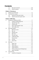
Using the dual function power switch 3-2 Chapter 4: BIOS setup 4.1 Managing and updating your BIOS 4-1 4.1.1 Creating a bootable floppy disk 4-1 4.1.2 ASUS EZ Flash utility 4-2 4.1.3 AFUDOS utility 4-3 4.1.4 ASUS CrashFree BIOS 2 utility 4-5 4.1.5 ASUS Update utility 4-7 4.2 BIOS setup program - Asus P5VD1-X | P5VD1-X User's Manual for English Edition - Page 5
support 5.1 Installing an operating system 5-1 5.2 Support CD information 5-1 5.2.1 Running the support CD 5-1 5.2.2 Drivers menu 5-2 5.2.3 Utilities menu 5-3 5.2.4 Manuals menu 5-4 5.2.5 ASUS Contact information 5-5 5.2.6 Other information 5-5 5.3 Software information 5-7 5.4 VIA RAID - Asus P5VD1-X | P5VD1-X User's Manual for English Edition - Page 6
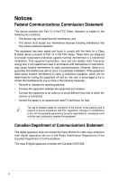
. This equipment generates, uses and can radiate radio frequency energy and, if not installed and used in accordance with manufacturerʼs instructions, may cause harmful interference to radio communications. However, there is no guarantee that interference will not occur in a particular installation - Asus P5VD1-X | P5VD1-X User's Manual for English Edition - Page 7
system. • When adding or removing devices to or from the system service technician or your retailer. Operation safety • Before installing the motherboard and adding devices on it, carefully read all the manuals encounter technical problems with the product, contact a qualified service technician or - Asus P5VD1-X | P5VD1-X User's Manual for English Edition - Page 8
of the BIOS parameters are also provided. • Chapter 5: Software support This chapter describes the contents of the support CD that comes with the motherboard package. Where to find more information Refer to the following sources for additional information and for product and software updates. 1. ASUS - Asus P5VD1-X | P5VD1-X User's Manual for English Edition - Page 9
of the following symbols used throughout this manual. DANGER/WARNING: Information to prevent injury to yourself when trying to complete a task. CAUTION: Information to prevent damage to the components when trying to complete a task. IMPORTANT: Instructions that you MUST follow to complete a task - Asus P5VD1-X | P5VD1-X User's Manual for English Edition - Page 10
cations Summary CPU Chipset Front Side Bus Memory Expansion slots Storage/RAID Audio LAN Overclocking Features USB Other ASUS Special Features BIOS features LGA775 socket for Intel® Pentium® D/Pentium® 4/Celeron CPU Supports Intel® Hyper-Threading Technology Northbridge: VIA PT880Ultra Southbridge - Asus P5VD1-X | P5VD1-X User's Manual for English Edition - Page 11
power connector System panel connector CD/AUX audio-in connectors Front panel Audio connector Drivers ASUS PC Probe ASUS Live Update Utility Anti-virus software (OEM version) 1 x Serial ATA cable 1 x SATA power cable 1 x UltraDMA 133/100/66 cable 1 x FDD cable 1 x I/O Shield Userʼs manual ATX form - Asus P5VD1-X | P5VD1-X User's Manual for English Edition - Page 12
xii - Asus P5VD1-X | P5VD1-X User's Manual for English Edition - Page 13
This chapter describes the motherboard features and the new technologies IntroPdruo1cdtuiocnt it supports. - Asus P5VD1-X | P5VD1-X User's Manual for English Edition - Page 14
Chapter Summary 1.1 Welcome 1-1 1.2 Package contents 1-1 1.3 Special features 1-2 ASUS P5VD1-X Motherboard - Asus P5VD1-X | P5VD1-X User's Manual for English Edition - Page 15
package for the following items. Motherboard ASUS P5VD1-X motherboard Cables 1 x Serial ATA signal cable 1 x Serial ATA power cable 1 x Ultra DMA 133/100/66 cable 1 x FDD cable Accessories I/O shield Application CDs ASUS Motherboard Support CD Documentation User guide If any of the above - Asus P5VD1-X | P5VD1-X User's Manual for English Edition - Page 16
any memory existing solutions in the market. System bottlenecks are eliminated with balanced architecture and peak bandwidths up to 6.4GB/s. PCI Express & AGP8X This motherboard supports PCI Express x16 and AGP8X slots to provide ultimate flexibility for graphics card upgrade. The PCI Express x16 - Asus P5VD1-X | P5VD1-X User's Manual for English Edition - Page 17
capability. 64-bit CPU support 64-bit computing, the next generation technology to replace current 32-bit architecture, delivers advanced system performance, faster memory access and increased productivity. This motherboard provides excellent compatibility and flexibility by supporting either 64-bit - Asus P5VD1-X | P5VD1-X User's Manual for English Edition - Page 18
2 The CrashFree BIOS2 feature now includes the BIOS auto-recovery function in a support CD. Users can reboot their system through the support CD when a bootable disk is not available, and go through the simple BIOS auto-recovery process. ASUS motherboards now enable users to enjoy this protection - Asus P5VD1-X | P5VD1-X User's Manual for English Edition - Page 19
This chapter lists the hardware setup procedures that you have to perform when installing system components. It includes description of the jumpers and connectors on the motherboard. 2 Hardware Information - Asus P5VD1-X | P5VD1-X User's Manual for English Edition - Page 20
Chapter Summary 2.1 Before you proceed 2-1 2.2 Motherboard overview 2-2 2.3 Central Processing Unit (CPU 2-4 2.4 System memory 2-9 2.5 Expansion slots 2-13 2.6 Jumpers 2-16 2.7 Connectors 2-18 ASUS P5VD1-X Motherboard - Asus P5VD1-X | P5VD1-X User's Manual for English Edition - Page 21
a reminder that you should shut down the system and unplug the power cable before removing or plugging in any motherboard component. The illustration below shows the location of the onboard LED. P5VD1-X ® P5VD1-X Onboard LED SB_PWR ON Standby Power OFF Powered Off ASUS P5VD1-X Motherboard 2-1 - Asus P5VD1-X | P5VD1-X User's Manual for English Edition - Page 22
or removing the motherboard. Failure to do so can cause you physical injury and damage motherboard components. 2.2.1 Placement direction When installing the motherboard, make sure indicated by circles to secure the motherboard to the chassis. Do not overtighten the screws! Doing so can damage the - Asus P5VD1-X | P5VD1-X User's Manual for English Edition - Page 23
CPU_FAN VIA PT880Ultra PRI_IDE Intel 82540EM AD1888 CD AUX FP_AUDIO AGP CR2032 3V Lithium Cell CMOS Power P5VD1-X PCIEX16 ® PCI1 VIA VT8237R CHA_FAN SATA1 SATA2 PCI2 SB_PWR PCI3 FLOPPY 4Mb BIOS USBPW56 USBPW78 USB56 USB78 GAME Super I/O PANEL CLRTC SEC_IDE ASUS P5VD1-X Motherboard 2-3 - Asus P5VD1-X | P5VD1-X User's Manual for English Edition - Page 24
with a surface mount LGA775 socket designed for the Intel® Pentium® 4 processor in the 775-land package. • Your boxed Intel® Pentium® 4 LGA775 processor package should come with installation instructions for the CPU, fan and heatsink assembly. If the instructions in this section do not match the - Asus P5VD1-X | P5VD1-X User's Manual for English Edition - Page 25
load B plate window to remove (B). Load plate 5. P o s i t i o n t h e C P U o v e r the socket, making sure that the gold triangle is on the bottom-left corner of the socket. The socket alignment key should fit into Alignment key the CPU notch. Gold triangle mark ASUS P5VD1-X Motherboard A 2-5 - Asus P5VD1-X | P5VD1-X User's Manual for English Edition - Page 26
info/hyperthreading. To use the Hyper-Threading Technology on this motherboard: 1. Install an Intel® Pentium® 4 CPU that supports Hyper-Threading Technology. 2. Power up the system and enter the BIOS Setup (see Chapter 4: BIOS setup). Under the Advanced Menu, make sure that the item Hyper-Threading - Asus P5VD1-X | P5VD1-X User's Manual for English Edition - Page 27
thermal condition and performance. • Install the motherboard to the chassis before you install the CPU fan and heatsink assembly • When you buy a boxed Intel® Pentium® 4 processor, the package includes the CPU fan and heatsink assembly. If you buy a CPU separately, make sure that you use only - Asus P5VD1-X | P5VD1-X User's Manual for English Edition - Page 28
in place. 3. When the fan and heatsink assembly is in place, connect the CPU fan cable to the connector on the motherboard labeled CPU_FAN. CPU_FAN P5VD1-X ® P5VD1-X CPU Fan connector Do not forget to connect the CPU fan connector! Hardware monitoring errors can occur if you fail to plug this - Asus P5VD1-X | P5VD1-X User's Manual for English Edition - Page 29
chipset resource allocation, the system may detect less than 4 GB system memory whne you installed four 1 GB DDR memory modules. • Due to chipset limitation, DIMM modules with 128 Mb memory chips or double-sided x16 memory chips are not supported in this motherboard. ASUS P5VD1-X Motherboard 2-9 - Asus P5VD1-X | P5VD1-X User's Manual for English Edition - Page 30
DDR400 Qualified Vendors List Size 256MB 512MB 256MB 512MB 256MB 512MB 256MB 512MB 256MB PSC Mosel SAMSUNG PSC Hynix Pmi Pmi Mosel Hynix KINGMAX KINGMAX Mosel Mosel NANYA NANYA DIMM support Side(s) Component A* B* C* SS HY5DU56822BT-D43 DS HY5DU56822BT-D43 SS A2S56D30BTP SS HY5DU12822BT-D43 - Asus P5VD1-X | P5VD1-X User's Manual for English Edition - Page 31
DDR400 Qualified Vendors List Size 256MB 512MB 256MB 512MB 256MB 256MB 512MB 512MB of Dual-channel memory configuration. C - support for 4 modules inserted into the blue and black slots as two pairs of Dualchannel memory configuration. SS - Single-sided DS - Double-sided ASUS P5VD1-X Motherboard 2- - Asus P5VD1-X | P5VD1-X User's Manual for English Edition - Page 32
adding or removing DIMMs or other system components. Failure to do so may cause severe damage to both the motherboard and the components. 1. Unlock the retaining clips outward to unlock the DIMM. 1 1 DDR DIMM notch Support the DIMM lightly with your fingers when pressing the retaining clips. The - Asus P5VD1-X | P5VD1-X User's Manual for English Edition - Page 33
expansion cards that they support. Make sure to system and change the necessary BIOS settings, if any. See Chapter 4 for information on BIOS setup. 2. Assign an IRQ to the card. Refer to the tables on the next page. 3. Install the software drivers for the expansion card. ASUS P5VD1-X Motherboard - Asus P5VD1-X | P5VD1-X User's Manual for English Edition - Page 34
)* IRQ holder for PCI steering* IRQ holder for PCI steering* Floppy Disk Controller Printer Port (LPT1)* System CMOS/Real Time Clock IRQ holder for PCI steering* IRQ holder for PCI steering* IRQ holder for PCI steering* PS/2 Compatible Mouse Port* Numeric Data Processor Primary IDE Channel Secondary - Asus P5VD1-X | P5VD1-X User's Manual for English Edition - Page 35
P5VD1-X Accelerated Graphics Port (AGP) 2.5.6 Universal PCI Express x16 slot This motherboard supports universal PCI Express x16 graphic cards that comply with the PCI Express specifications. The figure shows a graphics card installed on the universal PCI Express x16 slot. ASUS P5VD1-X Motherboard - Asus P5VD1-X | P5VD1-X User's Manual for English Edition - Page 36
1.B (BIOS: V5.43.02.16.E1) Pass Leadtek WinFast PX6600 TDH Rev. A1 (BIOS: V5.43.02.16) Gigabyte GV-RX70P128D Rev: 1.1 (BIOS: V009.004.001.032) Pass MSI RX700PRO-TD128E Rev.V2.00 (BIOS: V009.004.001.032) PCIe _ 4X Pass Pass Pass Pass Pass Pass Pass Pass Pass Pass Pass ASUS P5VD1-X Motherboard - Asus P5VD1-X | P5VD1-X User's Manual for English Edition - Page 37
Albatron PC6600GT (BIOS: V5.43.02.16) PowerColor R43-TVD3B Rev. PN:109-A31900-00 (BIOS: V5d57.9.3.1.20) Pass ASUS EAX850PRO (BIOS: V5D4F.9.7.1.4.AS02) PCIe _ 4X Pass Pass Pass Pass Pass Pass *Note: Some PCI Express graphics cards cannot operate on PCI-E x4 mode. ASUS P5VD1-X Motherboard 2-17 - Asus P5VD1-X | P5VD1-X User's Manual for English Edition - Page 38
® P5VD1-X Clear RTC RAM CLRTC 12 23 Normal (Default) Clear CMOS You do not need to clear the RTC when the system hangs due to overclocking. For system failure due to overclocking, use the C.P.R. (CPU Parameter Recall) feature. Shut down and reboot the system so the BIOS can automatically reset - Asus P5VD1-X | P5VD1-X User's Manual for English Edition - Page 39
wake up the computer from S1 sleep mode (CPU stopped, DRAM refreshed, system running in low power mode) using the system would not power up. • The total current consumed must NOT exceed the power supply capability (+5VSB) whether under normal condition or in sleep mode. ASUS P5VD1-X Motherboard - Asus P5VD1-X | P5VD1-X User's Manual for English Edition - Page 40
LAN (RJ-45) port. This port allows Gigabit connection to a Local Area Network (LAN) through a network hub. Refer to the table below for the LAN port LED indications. LAN SPEED LED LED LAN port 4. Line In jack. This Line In (light blue) jack connects a tape player or other audio sources. In 6- - Asus P5VD1-X | P5VD1-X User's Manual for English Edition - Page 41
connecting USB 2.0 devices. 9. Serial connector. This 9-pin COM1 port is for serial devices. 10. Coaxial S/PDIF Out port. This port connects an external audio output device via a coaxial S/PDIF cable. 11. PS/2 keyboard port (purple). This port is for a PS/2 keyboard. ASUS P5VD1-X Motherboard 2-21 - Asus P5VD1-X | P5VD1-X User's Manual for English Edition - Page 42
-X ® PIN 1 NOTE: Orient the red markings on the floppy ribbon cable to PIN 1. P5VD1-X Floppy disk drive connector 2. Primary/Secondary IDE connector (40-1 pin PRI_IDE, SEC_IDE) This connector supports the provided UltraATA133 IDE hard disk ribbon cable. Connect the cableʼs blue connector to the - Asus P5VD1-X | P5VD1-X User's Manual for English Edition - Page 43
Serial ATA RAID feature (RAID 0, RAID 1) is available only if you are using Windows® 2000/XP. • Install the Windows® 2000 Service Pack 4 or the Windows® XP Service Pack1 or later version before using Serial ATA. • VIA 8237/8237R Southbridge chipsets do not provide forwards compatibility with SATA-II - Asus P5VD1-X | P5VD1-X User's Manual for English Edition - Page 44
system may damage the motherboard components. These are not jumpers! DO NOT place jumper caps on the fan connectors. CPU_FAN CHA_FAN P5VD1-X ® P5VD1-X system chassis. These USB connectors comply with USB 2.0 specification that supports up to 480 Mbps connection speed. CPU FAN PWM CPU FAN IN CPU FAN - Asus P5VD1-X | P5VD1-X User's Manual for English Edition - Page 45
system motherboard power requirement test with the following configuration: CPU : Memory : Graphics card : Parallel ATA devices : Serial ATA device : Optical drives : SCSI devices : Intel® Pentium® 4 3.6 GHz 512 MB DDR (x 4) PCI Express x16 Nvidia EN5900 IDE hard disk drive (x 2) SATA - Asus P5VD1-X | P5VD1-X User's Manual for English Edition - Page 46
allow you to receive stereo audio input from sound sources such as a CD-ROM, TV tuner, or MPEG card. P5VD1-X ® CD(Black) Left Audio Channel Ground Ground Right Audio Channel AUX(White) Left Audio Channel Ground Ground Right Audio Channel P5VD1-X Internal audio connectors 8. GAME port connector - Asus P5VD1-X | P5VD1-X User's Manual for English Edition - Page 47
MIC2 MICPWR Line out_R NC Line out_L P5VD1-X Front panel audio connector Be default, the pins labeled LINE OUT_R/BLINE_OUT_R and the pins LINE OUT_L/BLINE_OUT_L are shorted with jumper caps. Remove the caps only when you are connecting the front panel audio cable. ASUS P5VD1-X Motherboard 2-27 - Asus P5VD1-X | P5VD1-X User's Manual for English Edition - Page 48
(20-pin PANEL) This connector supports several chassis-mounted functions. PLED SPEAKER PLED+ PLED+5V Ground Ground Speaker PANEL IDE_LED+ IDE_LED- PWR Ground Reset Ground P5VD1-X ® RESET IDE_LED PWRSW * Requires an ATX power supply. P5VD1-X System Panel connector The sytem panel - Asus P5VD1-X | P5VD1-X User's Manual for English Edition - Page 49
This chapter describes the power up sequence, the vocal POST messages, and ways of shutting down the system. 3 Powering Up - Asus P5VD1-X | P5VD1-X User's Manual for English Edition - Page 50
Chapter Summary 3.1 Starting up for the first time 3-1 3.2 Powering off the computer 3-2 ASUS P5VD1-X Motherboard - Asus P5VD1-X | P5VD1-X User's Manual for English Edition - Page 51
at the back of the system chassis. 4. Connect the controller error Refresh Time error No master drive detected Floppy controller failure Hardware component failure 7. At power on, hold down the key to enter the BIOS Setup. Follow the instructions in Chapter 4. ASUS P5VD1-X Motherboard - Asus P5VD1-X | P5VD1-X User's Manual for English Edition - Page 52
3. The power supply should turn off after Windows® shuts down. 3.2.2 Using the dual function power switch While the system is ON, pressing the power switch for less than four seconds puts the system to sleep mode or to soft-off mode, depending on the BIOS setting. Pressing the power switch for more - Asus P5VD1-X | P5VD1-X User's Manual for English Edition - Page 53
This chapter tells how to change the system settings through the BIOS Setup menus. Detailed descriptions of the BIOS parameters are also provided. 4 BIOS Setup - Asus P5VD1-X | P5VD1-X User's Manual for English Edition - Page 54
Chapter Summary 4.1 Managing and updating your BIOS 4-1 4.2 BIOS setup program 4-10 4.3 Main menu 4-13 4.4 Advanced menu 4-16 4.5 Power menu 4-25 4.6 Boot menu 4-29 4.7 Exit menu 4-33 ASUS P5VD1-X Motherboard - Asus P5VD1-X | P5VD1-X User's Manual for English Edition - Page 55
floppy disk.) 2. ASUS EZ Flash (Updates the BIOS using a floppy disk during POST.) 3. ASUS CrashFree BIOS 2 (Updates the BIOS using a bootable floppy disk or the motherboard support CD when the BIOS file fails or gets corrupted.) 4. ASUS Update (Updates the BIOS in Windows® environment.) Refer to - Asus P5VD1-X | P5VD1-X User's Manual for English Edition - Page 56
1. Visit the ASUS website (www.asus.com) to download the latest BIOS file for the motherboard and rename the same to P5VD1-X.ROM. 2. Save the BIOS file to a floppy disk, then restart the system. 3. Press + during POST to display the following. EZFlash starting BIOS update Checking for floppy - Asus P5VD1-X | P5VD1-X User's Manual for English Edition - Page 57
current BIOS file to the floppy disk. A:\>afudos /oOLDBIOS1.ROM AMI Firmware Update Utility - Version 1.10 Copyright (C) 2002 American Megatrends, Inc. All rights reserved. Reading flash ..... done A:\> The utility returns to the DOS prompt after copying the current BIOS file. ASUS P5VD1-X Motherboard - Asus P5VD1-X | P5VD1-X User's Manual for English Edition - Page 58
Updating the BIOS file To update the BIOS file using the AFUDOS utility: 1. Visit the ASUS website (www.asus.com) and download the latest BIOS file for the motherboard. Save the BIOS file to a bootable floppy disk. Write the BIOS filename on a piece of paper. You need to type the exact BIOS filename at the - Asus P5VD1-X | P5VD1-X User's Manual for English Edition - Page 59
support CD or the floppy disk containing the updated motherboard BIOS before using this utility. • Make sure that you rename the original or updated BIOS file in the floppy disk to P5VD1-X.ROM. Recovering the BIOS from a floppy disk To recover the BIOS from a floppy disk: 1. Turn on the system - Asus P5VD1-X | P5VD1-X User's Manual for English Edition - Page 60
down or reset the system while updating the BIOS! Doing so can cause system boot failure! 4. Restart the system after the utility completes the updating process. The recovered BIOS may not be the latest BIOS version for this motherboard. Visit the ASUS website (www.asus.com) to download the latest - Asus P5VD1-X | P5VD1-X User's Manual for English Edition - Page 61
The Drivers menu appears. 2. Click the Utilities tab, then click Install ASUS Update VX.XX.XX. See page 5-3 for the Utilities screen menu. 3. The ASUS Update utility is copied to your system. Quit all Windows® applications before you update the BIOS using this utility. ASUS P5VD1-X Motherboard 4-7 - Asus P5VD1-X | P5VD1-X User's Manual for English Edition - Page 62
through the Internet To update the BIOS through the Internet: 1. Launch the ASUS Update utility from the Windows® desktop by clicking Start > Programs > ASUS > ASUSUpdate > ASUSUpdate. The ASUS Update main window appears. 2. Select Update BIOS from the 3. Select the ASUS FTP site nearest Internet - Asus P5VD1-X | P5VD1-X User's Manual for English Edition - Page 63
> ASUSUpdate. The ASUS Update main window appears. 2. Select Update BIOS from a file option from the drop-down menu, then click Next. 3. Locate the BIOS file from the Open window, then click Save. 4. Follow the screen instructions to complete the update process. ASUS P5VD1-X Motherboard 4-9 - Asus P5VD1-X | P5VD1-X User's Manual for English Edition - Page 64
setup program This motherboard supports a programmable firmware chip that you can update using the provided utility described in section "4.1 Managing and updating your BIOS." Use the BIOS Setup program when you are installing a motherboard, reconfiguring your system, or prompted to "Run Setup". This - Asus P5VD1-X | P5VD1-X User's Manual for English Edition - Page 65
4.2.1 BIOS menu screen Menu items Menu bar Configuration fi the basic system configuration For changing the advanced system settings For changing the advanced power management (APM) configuration For changing the system boot confi keys differ from one screen to another. ASUS P5VD1-X Motherboard 4-11 - Asus P5VD1-X | P5VD1-X User's Manual for English Edition - Page 66
of the menu screen is a brief description of the selected item. Advanced Chipset settings WARNING: Setting wrong values in the sections below may cause system to malfunction. Configure DRAM Timing by SPD Memory Acceleration Mode DRAM Idle Timer DRAm Refresh Rate [Enabled] [Auto] [Auto] [Auto - Asus P5VD1-X | P5VD1-X User's Manual for English Edition - Page 67
of the basic system information. Refer to section "4.2.1 BIOS menu screen" for information on the menu screen items and how to navigate through them. System Time System Date Legacy 5.25 in.] [1.2M , 5.25 in.] [720K , 3.5 in.] [1.44M, 3.5 in.] [2.88M, 3.5 in.] ASUS P5VD1-X Motherboard 4-13 - Asus P5VD1-X | P5VD1-X User's Manual for English Edition - Page 68
system. ←→ Select Screen ↑↓ Select Item +- Change Option F1 General Help F10 Save and Exit ESC Exit v02.58 (C)Copyright 1985-2004, American Megatrends, Inc. The BIOS mode. Setting to Auto enables the LBA mode if the device supports this mode, and if the device was not previously formatted - Asus P5VD1-X | P5VD1-X User's Manual for English Edition - Page 69
05 Processor Type Speed Count : Intel(R) Pentium(R) 4 CPU 2.80GHz : 2800MHz : 1 System Memory Size : 256MB AMI BIOS Displays the auto-detected BIOS information Processor Displays the auto-detected CPU specification System Memory Displays the auto-detected system memory ASUS P5VD1-X Motherboard - Asus P5VD1-X | P5VD1-X User's Manual for English Edition - Page 70
CPU Configuration Chipset Onboard Devices Configuration PCIPnP 4.4.1 v02.58 (C)Copyright 1985-2004, American Megatrends, Inc. JumperFree Configuration Configure System Frequency/Voltage AI Overclocking Tuner CPU Frequency AGP/PCI Frequency [Manual %] [OverSpectrum 0.50%] 4-16 Chapter 4: BIOS Setup - Asus P5VD1-X | P5VD1-X User's Manual for English Edition - Page 71
] Allows you to configure the USB 2.0 controller in HiSpeed (480 Mbps) or Full Speed (12 Mbps). Configuration options: [Full Speed] [HiSpeed] BIOS EHCI Hand-Off [Enabled] Allows you to enable or disable the USB 2.0 function. Configuration options: [Disabled] [Enabled] ASUS P5VD1-X Motherboard 4-17 - Asus P5VD1-X | P5VD1-X User's Manual for English Edition - Page 72
Thermal Control [Auto] Disables or sets the CPU internal thermal control. Configuration options: [Auto] [Disabled] Hyper-Threading Technology [Disabled] Allows you to enable or disable the processor Hyper-Threading Technology Configuration options: [Disabled] [Enabled] 4-18 Chapter 4: BIOS Setup - Asus P5VD1-X | P5VD1-X User's Manual for English Edition - Page 73
DRAM Clock/Timing Configuration AGP & P2P Bridge Configuration V-Link & PCI Bus Configuration Options for DRAM Enter F1 F10 ESC Select Screen Select Item Go to Sub Screen General Help Save and Exit Exit v02.58 (C)Copyright 1985-2004, American Megatrends, Inc. ASUS P5VD1-X Motherboard 4-19 - Asus P5VD1-X | P5VD1-X User's Manual for English Edition - Page 74
Trcd) DRAM BUS Selection [Auto] [Maunel] [2.5] [5T] [20T] [5T] [Auto] Manual DRAM Frequency Setting or AUTO by SPD. ←→ Select Screen ↑↓ Select Item +- Change Option F1 DRAM BUS Selection [Single Channel] Configuration options: [Auto] [Single Channel] [Dual Channel] 4-20 Chapter 4: BIOS Setup - Asus P5VD1-X | P5VD1-X User's Manual for English Edition - Page 75
Write AGP Aperture Size Primary Graphics Adapter [8x] [Enabled] [128MB] [PCI Express] Select Option To Set AGP MODE. ←→ Select Screen ↑↓ Select Item +- 1] [Mode 2] [Mode 3] [Mode 4] V-Link Data 2X Support [Disabled] Configuration options: [Disabled] [Enabled] ASUS P5VD1-X Motherboard 4-21 - Asus P5VD1-X | P5VD1-X User's Manual for English Edition - Page 76
2004, American Megatrends, Inc. PCI Delay Transaction [Disabled] Configuration options: [Disabled] [Enabled] OnBoard SATA-IDE [RAID] Configuration options: [Disabled] [SATA] [RAID] RAID BIOS Execute [Enabled] Configuration options: [Disabled] [Enabled] OnBoard ACʼ97 Audio [Enabled] Configuration options - Asus P5VD1-X | P5VD1-X User's Manual for English Edition - Page 77
OnBoard LAN [Enabled] Allows you to enable or disable the onboard PCI Express Gigabit LAN controller. Configuration options: [Disabled] [Enabled] OnBoard LAN Boot ROM [Enabled] Allows you to enable or disable the OnBoard LAN Boot ROM. Configuration options: [Enabled] [Disabled] 4-23 Chapter 4: BIOS - Asus P5VD1-X | P5VD1-X User's Manual for English Edition - Page 78
that an ISA graphics device is installed in the system so that the latter can function correctly. Configuration options: [Disabled] [Enabled] IRQ-xx assigned to [PCI Device] When set to [PCI Device], the specific IRQ is free for use of PCI/PnP devices. When set to [Reserved], the IRQ is reserved - Asus P5VD1-X | P5VD1-X User's Manual for English Edition - Page 79
to enable or disable the Advanced Configuration and Power Interface (ACPI) support in the Application-Specific Integrated Circuit (ASIC). When set to Enabled, the ACPI APIC table pointer is included in the RSDT pointer list. Configuration options: [Disabled] [Enabled] ASUS P5VD1-X Motherboard 4-25 - Asus P5VD1-X | P5VD1-X User's Manual for English Edition - Page 80
[Last State] Select Disable Or Enable APM. Advanced Resume Events Controls Resume On Ring [Disabled] Resume On PME# [Disabled] Resume On Resume On KB [Disabled] Allows you to use specific keys on the keyboard to turn on the system. This feature requires an ATX power supply that 4: BIOS Setup - Asus P5VD1-X | P5VD1-X User's Manual for English Edition - Page 81
per minute (RPM). If the fan is not connected to the motherboard, the field shows Ingnored. CPU Q-Fan Control [Disabled] Allows you to enable or disable the ASUS Q-Fan feature that smartly adjusts the fan speeds for more efficient system operation. Configuration options: [Disabled] [Enabled] The - Asus P5VD1-X | P5VD1-X User's Manual for English Edition - Page 82
90%] [80%] [70%] [60%] [50%] [40%] [30%] [20%] CPU Target Temperature [xxºC] Allows you to set the CPU temperature threshold when the CPU fan speed is increased to lower the CPU temperature. This item appears only when the CPU Q-Fan Control item is Enabled. The configuration options vary depending on - Asus P5VD1-X | P5VD1-X User's Manual for English Edition - Page 83
the boot device priority sequence froEmnttehreGaovatoilaSbulbe-Sdcerveiecnes. The number of device items that appears on the screen deFFp11e0ndsGSeaonvneertaahlnedHneEulxmpitber of devices installed in the system. Configuration options: [xxxExSxCDrivEexi]t[Disabled] ASUS P5VD1-X Motherboard 4-29 - Asus P5VD1-X | P5VD1-X User's Manual for English Edition - Page 84
Num-Lock PS/2 Mouse Support Wait For 'F1' If Error Hit 'DEL' Message Display Interrupt 19 Capture [Enabled] [Enabled] [Force BIOS] [On] [Auto] [Enabled] [Enabled] [Disabled] Allows BIOS to skip certain tests while booting. This will decrease the time needed to boot the system. Quick Boot [Enabled - Asus P5VD1-X | P5VD1-X User's Manual for English Edition - Page 85
your BIOS password, you can clear clear it by erasing the CMOS Real Time Clock (RTC) RAM. See section "2.6 Jumpers" for information on how to erase the RTC RAM. After you have set a supervisor password, the other items appear to allow you to change other security settings. ASUS P5VD1-X Motherboard - Asus P5VD1-X | P5VD1-X User's Manual for English Edition - Page 86
wish to clear the user password. Password Check [Setup] When set to [Setup], BIOS checks for user password when accessing the Setup utility. When set to [Always], BIOS checks for user password both when accessing Setup and booting the system. Configuration options: [Setup] [Always] 4-32 Chapter - Asus P5VD1-X | P5VD1-X User's Manual for English Edition - Page 87
you made changes to fields other than System Date, System Time, and Password, the BIOS asks for a confirmation before exiting. window appears. Select Yes to load default values. Select Exit & Save Changes or make other changes before saving the values to the non-volatile RAM. ASUS P5VD1-X Motherboard - Asus P5VD1-X | P5VD1-X User's Manual for English Edition - Page 88
4-34 Chapter 4: BIOS Setup - Asus P5VD1-X | P5VD1-X User's Manual for English Edition - Page 89
Software Sup5port This chapter describes the contents of the support CD that comes with the motherboard package. - Asus P5VD1-X | P5VD1-X User's Manual for English Edition - Page 90
Chapter summary 5.1 Installing an operating system 5-1 5.2 Support CD information 5-1 5.3 Software information 5-7 5.4 VIA RAID configurations 5-14 5.5 Creating a RAID driver disk 5-18 ASUS P5VD1-X Motherboard - Asus P5VD1-X | P5VD1-X User's Manual for English Edition - Page 91
that you install Windows® 2000 Service Pack 4 or the Windows ® XP Service Pack 1 or later versions before installing the drivers for better compatibility and system stability. 5.2 Support CD information The support CD that came with the motherboard package contains the drivers, software applications - Asus P5VD1-X | P5VD1-X User's Manual for English Edition - Page 92
ASUS InstAll for Drivers InstAll for Drivers. VIA 4 in 1 Drivers Install VIA 4 in 1 Drivers. Make VIA RAID Driver Disk Make VIA RAID Driver Disk. Allow you to browse the path \Drivers\Chipset\DrvDisk to refer the uncompressed files. ADI Audio Driver Installl ADI Audio Driver. Intel Gigabit Ethernet - Asus P5VD1-X | P5VD1-X User's Manual for English Edition - Page 93
other software that the motherboard supports. ASUS InstAll for Utiliities Auto Install All Utilities. ASUS Update ASUS Update can help user to download and flash BIOS. Please install Network Card and TCP/IP network driver first, otherwise ASUS Update can not work properly. ASUS Screen Saver Installs - Asus P5VD1-X | P5VD1-X User's Manual for English Edition - Page 94
from the Utilities menu before opening the manual files. Intel LGA775 CPU Install Userʼs Manual Allows you to open the Intel® LGA775 CPU installation userʼs manual. The screen display and manuals option may not be the same for different operating system versions. 5-4 Chapter 5: Software support - Asus P5VD1-X | P5VD1-X User's Manual for English Edition - Page 95
guide. 5.2.6 Other information The icons on the top right corner of the screen give additional information on the motherboard and the contents of the support CD. Click an icon to display the specified information. Motherboard Info Displays the general specifications of the motherboard. ASUS P5VD1 - Asus P5VD1-X | P5VD1-X User's Manual for English Edition - Page 96
Browse this CD Displays the support CD contents in graphical format. Technical support Form Displays the ASUS Technical Support Request Form that you have to fill out when requesting technical support. Filelist Displays the contents of the support CD and a brief description of each in text format. - Asus P5VD1-X | P5VD1-X User's Manual for English Edition - Page 97
Select Update BIOS from a file from the drop down menu, then click Next. 5. When prompted, locate the new BIOS file, then click Next. The ASUS MyLogo2 window appears. 6. From the left window pane, select the folder that contains the image you intend to use as your boot logo. ASUS P5VD1-X Motherboard - Asus P5VD1-X | P5VD1-X User's Manual for English Edition - Page 98
7. When the logo images appear on the right window pane, select an image to enlarge by clicking on it. 8. Adjust the boot image to your desired size by selecting a value on the Ratio box. 9. When the screen returns to the ASUS Update utility, flash the original BIOS to load the new boot logo. 10. - Asus P5VD1-X | P5VD1-X User's Manual for English Edition - Page 99
configurations The motherboard includes a high performance IDE RAID controller integrated in the VIA VT8237R southbridge chipset. It supports RAID 0, RAID 1 and JBOD with two independent Serial ATA channels. RAID 0 (called Data striping) optimizes two identical hard disk drives to read and write data - Asus P5VD1-X | P5VD1-X User's Manual for English Edition - Page 100
The motherboard includes a high performance IDE RAID controller integrated in the VIA VT8237R southbridge chipset. It supports RAID 0 and RAID 1 with two independent Serial ATA channels. Setting the BIOS RAID items After installing the hard disk drives, make sure to set the necessary RAID items - Asus P5VD1-X | P5VD1-X User's Manual for English Edition - Page 101
to set up hard disk for RAID system. The following confirmation message appears: The data on the selected disks will be destroyed. Continue? (Y/N) 8. Press to confirm or to return to the configuration options. 9. Press to go back to main menu. ASUS P5VD1-X Motherboard 5-11 - Asus P5VD1-X | P5VD1-X User's Manual for English Edition - Page 102
supported RAID configurations appear on a pop-up menu. RAID 0 for performance RRAAIIDD 11 ffoorr ddaattaa pprrootteeccttiioonn RAID 0/1 RAID SPAN for capacity 2. Select RAID RAID array by selecting Auto Setup for Data Security or manually configure the RAID hard disk for RAID system. The following - Asus P5VD1-X | P5VD1-X User's Manual for English Edition - Page 103
the OS installation, the system prompts you to press the F6 key to install third-party SCSI or RAID driver. 2. Press then insert the floppy disk with RAID driver into the floppy disk drive. 3. Follow the succeeding screen instructions to complete the installation. ASUS P5VD1-X Motherboard 5-13 - Asus P5VD1-X | P5VD1-X User's Manual for English Edition - Page 104
5-14 Chapter 5: Software Support
-
 1
1 -
 2
2 -
 3
3 -
 4
4 -
 5
5 -
 6
6 -
 7
7 -
8
-
9
-
10
-
11
-
12
-
13
-
14
-
15
-
16
-
17
-
18
-
19
-
20
-
21
-
22
-
23
-
24
-
25
-
26
-
27
-
28
-
29
-
30
-
31
-
32
-
33
-
34
-
35
-
36
-
37
-
38
-
39
-
40
-
41
-
42
-
43
-
44
-
45
-
46
-
47
-
48
-
49
-
50
-
51
-
52
-
53
-
54
-
55
-
56
-
57
-
58
-
59
-
60
-
61
-
62
-
63
-
64
-
65
-
66
-
67
-
68
-
69
-
70
-
71
-
72
-
73
-
74
-
75
-
76
-
77
-
78
-
79
-
80
-
81
-
82
-
83
-
84
-
85
-
86
-
87
-
88
-
89
-
90
-
91
-
92
-
93
-
94
-
95
-
96
-
97
-
98
-
99
-
100
-
101
-
102
-
103
-
104
 |
 |

Motherboard
User Guide
P5VD1-X