Asus P5VDC-X Motherboard Installation Guide
Asus P5VDC-X Manual
 |
View all Asus P5VDC-X manuals
Add to My Manuals
Save this manual to your list of manuals |
Asus P5VDC-X manual content summary:
- Asus P5VDC-X | Motherboard Installation Guide - Page 1
P5VDC-X Motherboard - Asus P5VDC-X | Motherboard Installation Guide - Page 2
"). Product warranty or service will not be extended if: (1) the product is repaired, modified or altered, unless such repair, modification of alteration is authorized in writing by ASUS; or (2) the serial number of the product is defaced or missing. ASUS PROVIDES THIS MANUAL "AS IS" WITHOUT WARRANTY - Asus P5VDC-X | Motherboard Installation Guide - Page 3
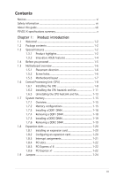
vii About this guide viii P5VDC-X specifications summary x Chapter 1: Product introduction 1.1 Welcome 1-2 1.2 Package contents 1-2 1.3 Special features 1-2 1.3.1 Product highlights 1-2 1.3.2 Innovative ASUS features 1-4 1.4 Before you proceed 1-5 1.5 Motherboard overview 1-6 1.5.1 Placement - Asus P5VDC-X | Motherboard Installation Guide - Page 4
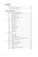
utility 2-4 2.1.4 ASUS CrashFree BIOS 2 utility 2-6 2.1.5 ASUS Update utility 2-8 2.2 BIOS setup program 2-11 2.2.1 BIOS menu screen 2-12 2.2.2 Menu bar 2-12 2.2.3 Navigation keys 2-12 2.2.4 Menu items 2-13 2.2.5 Sub-menu items 2-13 2.2.6 Configuration fields 2-13 2.2.7 Pop-up window 2-13 - Asus P5VDC-X | Motherboard Installation Guide - Page 5
Security 2-35 2.7 Exit menu 2-37 Chapter 3: Software support 3.1 Installing an operating system 3-2 3.2 Support CD information 3-2 3.2.1 Running the support CD 3-2 3.2.2 Drivers menu 3-3 3.2.3 Utilities menu 3-4 3.2.4 Make Disk 3-5 3.2.5 Manual menu 3-6 3.2.6 ASUS Contact information 3-7 v - Asus P5VDC-X | Motherboard Installation Guide - Page 6
. This equipment generates, uses and can radiate radio frequency energy and, if not installed and used in accordance with manufacturerʼs instructions, may cause harmful interference to radio communications. However, there is no guarantee that interference will not occur in a particular installation - Asus P5VDC-X | Motherboard Installation Guide - Page 7
service technician or your retailer. Operation safety • Before installing the motherboard and adding devices on it, carefully read all the manuals and staples away from connectors, slots, sockets and circuitry. • Avoid dust, technical problems with the product, contact a qualified service technician - Asus P5VDC-X | Motherboard Installation Guide - Page 8
installing and configuring the motherboard. How this guide is organized This manual contains the following parts: • Chapter 1: Product introduction This chapter describes the features of the motherboard and the new technology it supports. This chapter also lists the hardware setup procedures that - Asus P5VDC-X | Motherboard Installation Guide - Page 9
of the following symbols used throughout this manual. DANGER/WARNING: Information to prevent injury to yourself when trying to complete a task. CAUTION: Information to prevent damage to the components when trying to complete a task. IMPORTANT: Instructions that you MUST follow to complete a task - Asus P5VDC-X | Motherboard Installation Guide - Page 10
P5VDC-X specifications summary CPU Chipset Front Side Bus Memory Expansion slots Storage Audio LAN USB BIOS ASUS Special Features Rear panel LGA775 socket for Intel® Pentium® 4/ Pentium® D/ Celeron processors Supports Intel® Dual-Core 65nm Intel® processors Supports Intel® Hyper-Threading - Asus P5VDC-X | Motherboard Installation Guide - Page 11
-pin EATX power connector 1 x 4-pin ATX 12 V power connector 1 x Front panel audio connector 1 x CD audio-in connector CPU/Chassis/Power fan connectors ATX form factor: 12 in x 8.6 in Drivers ASUS PC Probe II ASUS Live Update utility Anti-virus software *Specifications are subject to change without - Asus P5VDC-X | Motherboard Installation Guide - Page 12
xii - Asus P5VDC-X | Motherboard Installation Guide - Page 13
This chapter describes the motherboard features and the new technologies it supports. 1Product introduction ASUS P5VDC-X 1-1 - Asus P5VDC-X | Motherboard Installation Guide - Page 14
CD ASUS motherboard support CD Documentation User guide If any of the above items is damaged or missing, contact your retailer. 1.3 Special features 1.3.1 Product highlights Latest processor technology The motherboard comes with a 775-pin surface mount Land Grid Array (LGA) socket designed - Asus P5VDC-X | Motherboard Installation Guide - Page 15
graphics card upgrade. The PCI Express x16 slot running at PCI Express x4 speed outperforms PCI interface with its exceptional high bandwidth up to 2GB/s. See page 1-22 for details. Dual Channel DDR and DDRII support Employing the Double Data Rate (DDR) memory technology, the motherboard supports up - Asus P5VDC-X | Motherboard Installation Guide - Page 16
allows you to restore the original BIOS data from the support CD in case when the BIOS codes and data are corrupted. This protection eliminates the need to buy a replacement ROM chip. See page 2-6 for details. ASUS MyLogo™ This new feature present in the motherboard allows you to personalize and add - Asus P5VDC-X | Motherboard Installation Guide - Page 17
• Unplug the power cord from the wall socket before touching any component. • Use a grounded cause severe damage to the motherboard, peripherals, and/or components. Onboard LED The motherboard comes with a standby power plugging in any motherboard component. The illustration below shows the location of - Asus P5VDC-X | Motherboard Installation Guide - Page 18
motherboard. Failure to do so can cause you physical injury and damage motherboard components. 1.5.1 Placement direction When installing the motherboard by circles to secure the motherboard to the chassis. Do not overtighten the screws! Doing so can damage the motherboard. Place this side towards - Asus P5VDC-X | Motherboard Installation Guide - Page 19
EATXPWR 30.5cm (12in) 1.5.3 Motherboard layout PS/2KBMS T:Mouse B:Keyboard COM1 ATX12V 21.8cm (8.6in) LGA775 PWR_FAN CPU_FAN PARALLEL PORT USB12 LAN_USB34 RTL8201CL P5VDC-X CHA_FAN AGP Super I/O PCIEX16 AD1986A CD AAFP PCI1 PCI2 USB78_WIFI PCI3 FLOPPY R VIA VT8237A 4Mb BIOS USBPW56 - Asus P5VDC-X | Motherboard Installation Guide - Page 20
Central Processing Unit (CPU) The motherboard comes with a surface mount LGA775 socket designed for the Intel® Pentium® 4/Pentium® D processor in the 775-land package. • Your boxed Intel® Pentium® 4 LGA775 processor package should come with installation instructions for the CPU, heatsink, and the - Asus P5VDC-X | Motherboard Installation Guide - Page 21
PnP cap from the load plate window to remove (B). B A Load plate 5. Position the CPU on the socket, making sure that the gold triangle fixes on the bottom-left corner of the socket. The socket alignment keys should fit into the CPU notches. Alignment key Gold triangle mark ASUS P5VDC-X 1-9 - Asus P5VDC-X | Motherboard Installation Guide - Page 22
benting the connectors on the socket and damaging the CPU. Notes on Intel® Hyper-Threading Technology • This motherboard supports Intel® Pentium® 4 processor in the 775land package with Hyper-Threading Technology. • Hyper-Threading Technology is supported under Windows® XP/2003 Server and Linux - Asus P5VDC-X | Motherboard Installation Guide - Page 23
condition and performance. • Install the motherboard to the chassis before you install the CPU fan and heatsink assembly. • When you buy a boxed Intel® Pentium® 4 processor, the package includes the CPU fan and heatsink assembly. • Your Intel® Pentium® 4 LGA775 heatsink and fan assembly comes in - Asus P5VDC-X | Motherboard Installation Guide - Page 24
heatsink and B fan assembly in place. A A B A B B A 3. Connect the CPU fan cable to the connector on the motherboard labeled CPU_FAN. Top:Line In Center:Line Out Below:Mic In P5VDC-X R CPU_FAN GND CPU FAN PWR CPU FAN IN CPU FAN PWM P5VDC-X CPU FAN Connector Do not forget to connect the - Asus P5VDC-X | Motherboard Installation Guide - Page 25
CPU heatsink and fan: 1. Disconnect the CPU fan cable from the connector on the motherboard. 2. Rotate each fastener counterclockwise. 3. Pull up two fasteners at a time in a diagonal sequence to disengage the heatsink B and fan assembly from the A A motherboard. B A B B A ASUS P5VDC - Asus P5VDC-X | Motherboard Installation Guide - Page 26
4. Remove the heatsink and fan assembly from the motherboard. 5. Rotate each fastener clockwise to reset the orientation. When reset, each fastener should be oriented as shown, with the narrow groove directed outward. Narrow end of the groove 1-14 Chapter 1: Hardware information - Asus P5VDC-X | Motherboard Installation Guide - Page 27
and DDR2_2 Top:Line In Center:Line Out Below:Mic In P5VDC-X R DDR2_B1 DDR2_A1 DDR_B1 DDR_A1 P5VDC-X DDR & DDR2 DIMM Sockets • To prevent damage to the motherboard, do not use DDR and DDR2 memory simultaneously. • Due to chipset resource allocation, the system may detect less than 2 GB system - Asus P5VDC-X | Motherboard Installation Guide - Page 28
one module inserted in any yellow slot. B - supports one pair of modules inserted into both of the yellow slots. SS - Single-sided DS - Double-sided DDR (400 MHz) Qualified Vendors List Size Vendor 256MB 256MB 512MB 512MB 512MB 512MB 512MB 512MB 256MB 256MB 256MB 1G 256MB 512MB 512MB Kingston - Asus P5VDC-X | Motherboard Installation Guide - Page 29
-J Legend: A - supports one module inserted in any blue slot. B - supports one pair of modules inserted into both of the blue slots. SS - Single-sided DS - Double-sided Visit the system builderʼs website for the latest DDR2-533, DDR-400, or DDR-333 Qualified Vendors List. ASUS P5VDC-X 1-17 - Asus P5VDC-X | Motherboard Installation Guide - Page 30
adding or removing DIMMs or other system components. Failure to do so may cause severe damage to both the motherboard and the components. 1. Unlock a DDR1 DIMM socket by pressing the retaining clips outward. 2. Align a DIMM on the socket such that the notch on the DIMM matches the break on the - Asus P5VDC-X | Motherboard Installation Guide - Page 31
1. Simultaneously press the retaining clips outward to 2 unlock the DIMM. Support the DIMM lightly with your fingers when pressing the retaining clips. The DIMM might get damaged when it flips out 1 with extra force. 1 DDR2 DIMM notch 2. Remove the DIMM from the socket. ASUS P5VDC-X 1-19 - Asus P5VDC-X | Motherboard Installation Guide - Page 32
the expansion cards that they support. Make sure to unplug the injury and damage motherboard components. 1.8.1 Installing Remove the system unit cover (if your motherboard is already installed in a chassis). the necessary BIOS settings, if any. See Chapter 2 for information on BIOS setup. 2. - Asus P5VDC-X | Motherboard Installation Guide - Page 33
PS/2 Compatible Mouse Port this motherboard PCI USB controller 3 Onboard USB controller 4 Onboard USB 2.0 controller Onboard LAN Onboard audio A B C D E F G H shared - - - When using PCI cards on shared slots, ensure that the drivers support "Share IRQ" or that the cards do not need IRQ - Asus P5VDC-X | Motherboard Installation Guide - Page 34
they fit the AGP slot on your motherboard. Install only 1.5 V or 0.8 V AGP cards on this motherboard! Top:Line In Center:Line Out Below:Mic In P5VDC-X R Keyed for 1.5v P5VDC-X Accelerated Graphics Port (AGP) 1.8.6 PCI Express x16 slot This motherboard supports PCI Express x16 graphic cards that - Asus P5VDC-X | Motherboard Installation Guide - Page 35
. V1.00 Rev. V1.00 Rev. V1.00A Rev. V1.00 Rev. B • Some PCI Express graphics cards cannot operate on PCIe x4 mode. • Visit the ASUS website for the latest VGA Qualified Vendors List. ASUS P5VDC-X 1-23 - Asus P5VDC-X | Motherboard Installation Guide - Page 36
the CMOS memory of date, P5VDC-X Clear RTC RAM CLRTC 12 23 Normal (Default) Clear CMOS You do not need to clear the RTC when the system hangs due to overclocking. For system failure due to overclocking, use the C.P.R. (CPU Parameter Recall) feature. Shut down and reboot the system so the BIOS - Asus P5VDC-X | Motherboard Installation Guide - Page 37
connected USB devices. Set to +5VSB to wake up from S3 and S4 sleep modes (no power to CPU, DRAM in slow refresh, power supply in reduced power mode). The USBPW12 and USBPW34 jumpers are for the the power supply capability (+5VSB) whether under normal condition or in sleep mode. ASUS P5VDC-X 1-25 - Asus P5VDC-X | Motherboard Installation Guide - Page 38
10M LED Status OFF GREEN BLINKING Description No link 10M speed Acting 100M LED 10M LED LAN port 4. Line In port (light blue). This port connects a tape, CD, DVD player, or other audio sources. 5. Line Out port (lime). This port connects a headphone or a speaker. In 4-channel, and 6-channel con - Asus P5VDC-X | Motherboard Installation Guide - Page 39
Audio 2, 4, or 6-channel configuration Port Light Blue Lime Pink Headset 2-channel Line In Line Out Mic In 4-channel when using a FDD cable with a covered Pin 5. Top:Line In Center:Line Out Below:Mic In P5VDC-X FLOPPY R PIN 1 NOTE: Orient the red markings on the floppy ribbon cable to PIN - Asus P5VDC-X | Motherboard Installation Guide - Page 40
cable: blue, black, and gray. Connect the blue connector to the motherboardʼs IDE connector, then select one of the following modes to confi same setting. PRI_IDE Top:Line In Center:Line Out Below:Mic In P5VDC-X R P5VDC-X IDE Connectors SEC_IDE NOTE: Orient the red markings (usually zigzag) on - Asus P5VDC-X | Motherboard Installation Guide - Page 41
RSATA_TXN2 GND P5VDC-X SATA Connectors Install the Windows® 2000 Service Pack 4 or the Windows® XP Service Pack1 before using Serial ATA. For detailed instructions on how to configure RAID 0,RAID 1, and JBOD, refer to the RAID manual in the support CD. See page 3-6 for details. ASUS P5VDC-X 1-29 - Asus P5VDC-X | Motherboard Installation Guide - Page 42
. Insufficient air flow inside the system may damage the motherboard components. These are not jumpers! Do not place jumper caps on the fan connectors! Top:Line In Center:Line Out Below:Mic In P5VDC-X R CPU_FAN GND CPU FAN PWR CPU FAN IN CPU FAN PWM PWR_FAN GND +12V Rotation CHA_FAN Rotation +12V - Asus P5VDC-X | Motherboard Installation Guide - Page 43
NC NC NC AGND SENSE2_RETUR SENSE1_RETUR PRESENCE# GND P5VDC-X Analog Front Panel Connector It is recommended that you connect a high-definition front panel audio module to this connector to avail of the motherboardʼs high-definition audio capability. ASUS P5VDC-X Analog Front Panel Connector 1-31 - Asus P5VDC-X | Motherboard Installation Guide - Page 44
EATXPWR Top:Line In Center:Line Out Below:Mic In P5VDC-X R +12V DC GND P5VDC-X ATX Power Connectors +12V DC GND +3 Volts -12 can also use a Power Supply Unit (PSU) with a 24-pin ATX power connector on this motherboard. • Do not forget to connect the 4-pin ATX +12 V power plug; otherwise, the - Asus P5VDC-X | Motherboard Installation Guide - Page 45
supports several chassis-mounted functions. Top:Line In Center:Line Out Below:Mic In P5VDC-X PLED SPEAKER PLED+ PLED+5V Ground Ground Speaker PANEL IDE_LED+ IDE_LED- PWR Ground Reset Ground R IDE_LED P5VDC or soft-off mode depending on the BIOS settings. Pressing the power switch for more - Asus P5VDC-X | Motherboard Installation Guide - Page 46
1-34 Chapter 1: Hardware information - Asus P5VDC-X | Motherboard Installation Guide - Page 47
This chapter tells how to change the system settings through the BIOS Setup menus. Detailed descriptions of the BIOS parameters are also provided. 2 BIOS setup ASUS P5VDC-X 2-1 - Asus P5VDC-X | Motherboard Installation Guide - Page 48
floppy disk.) 2. ASUS EZ Flash (Updates the BIOS using a floppy disk during POST.) 3. ASUS CrashFree BIOS 2 (Updates the BIOS using a bootable floppy disk or the motherboard support CD when the BIOS file fails or gets corrupted.) 4. ASUS Update (Updates the BIOS in Windows® environment.) Refer to - Asus P5VDC-X | Motherboard Installation Guide - Page 49
pressing + during the Power-On Self-Test (POST). To update the BIOS using EZ Flash: 1. Visit the ASUS website (www.asus.com) to download the latest BIOS file for the motherboard and rename the same to P5VDCX.ROM. 2. Save the BIOS file to a floppy disk, then restart the system. 3. Press - Asus P5VDC-X | Motherboard Installation Guide - Page 50
at least 600 KB free space to save the file. • The succeeding BIOS screens are for reference only. The actual BIOS screen displays may not be exactly the same as shown. 1. Copy the AFUDOS utility (afudos.exe) from the motherboard support CD to the bootable floppy disk you created earlier. 2. Boot the - Asus P5VDC-X | Motherboard Installation Guide - Page 51
Updating the BIOS file To update the BIOS file using the AFUDOS utility: 1. Visit the ASUS website (www.asus.com) and download the latest BIOS file for the motherboard. Save the BIOS file to a bootable floppy disk. Write the BIOS filename on a piece of paper. You need to type the exact BIOS filename at - Asus P5VDC-X | Motherboard Installation Guide - Page 52
disk that contains the updated BIOS file. • Prepare the motherboard support CD or the floppy disk containing the updated motherboard BIOS before using this utility. • Make sure that you rename the original or updated BIOS file in the floppy disk to P5VDC-X.ROM. Recovering the BIOS from a floppy disk To - Asus P5VDC-X | Motherboard Installation Guide - Page 53
while updating the BIOS! Doing so can cause system boot failure! 4. Restart the system after the utility completes the updating process. The recovered BIOS may not be the latest BIOS version for this motherboard. Visit the ASUS website (www.asus.com) to download the latest BIOS file. ASUS P5VDC - Asus P5VDC-X | Motherboard Installation Guide - Page 54
you to manage, save, and update the motherboard BIOS in Windows® environment. The ASUS Update utility allows you to: • Save the current BIOS file • Download the latest BIOS file from the Internet • Update the BIOS from an updated BIOS file • Update the BIOS directly from the Internet, and • View - Asus P5VDC-X | Motherboard Installation Guide - Page 55
Start > Programs > ASUS > ASUSUpdate > ASUSUpdate. The ASUS Update main window appears. 2. Select Update BIOS from the Internet option from the drop-down menu, then click Next. 3. Select the ASUS FTP site nearest you to avoid network traffic, or click Auto Select. Click Next. ASUS P5VDC-X 2-9 - Asus P5VDC-X | Motherboard Installation Guide - Page 56
wish to download. Click Next. 5. Follow the screen instructions to complete the update process. The ASUS Update utility is capable of updating itself through the Internet. Always update the utility to avail all its features. Updating the BIOS through a BIOS file To update the BIOS through a BIOS file - Asus P5VDC-X | Motherboard Installation Guide - Page 57
under the Exit Menu. See section "2.7 Exit Menu." • The BIOS setup screens shown in this section are for reference purposes only, and may not exactly match what you see on your screen. • Visit the ASUS website (www.asus.com) to download the latest BIOS file for this motherboard. ASUS P5VDC-X 2-11 - Asus P5VDC-X | Motherboard Installation Guide - Page 58
2.2.1 BIOS menu screen Menu items Menu bar Configuration fields General help System Time System Date Legacy Diskette A Primary IDE Master Primary IDE Slave select items in the menu and change the settings. Some of the navigation keys differ from one screen to another. 2-12 Chapter 2: BIOS setup - Asus P5VDC-X | Motherboard Installation Guide - Page 59
of the selected item. Advanced Chipset settings WARNING: Setting wrong values in the sections below may cause system to malfunction. Configure DRAM Timing by SPD Memory Acceleration Mode DRAM Idle Timer F1 General Help F10 Save and Exit ESC Exit Pop-up window Scroll bar ASUS P5VDC-X 2-13 - Asus P5VDC-X | Motherboard Installation Guide - Page 60
screen appears, giving you an overview of the basic system information. Refer to section "2.2.1 BIOS menu screen" for information on the menu screen items and how to navigate through them. 5.25 in.] [1.2M , 5.25 in.] [720K , 3.5 in.] [1.44M, 3.5 in.] [2.88M, 3.5 in.] 2-14 Chapter 2: BIOS setup - Asus P5VDC-X | Motherboard Installation Guide - Page 61
Supported Type LBA/Large Mode Block(Multi-sector Transfer) M PIO Mode DMA Mode Smart Monitoring 32Bit Data Transfer [Auto] [Auto] [Auto] [Auto] [Auto] [Auto] [Enabled] The BIOS the LBA mode if the device supports this mode, and if the time if the device supports multi-sector transfer feature. - Asus P5VDC-X | Motherboard Installation Guide - Page 62
: 0117 Build Date : 03/20/06 Processor Type : Genuine Intel(R) CPU 2.80GHz Speed : 2800 MHz Count : 2 System Memory Size : 256MB AMI BIOS Displays the auto-detected BIOS information Processor Displays the auto-detected CPU specification System Memory Displays the auto-detected system - Asus P5VDC-X | Motherboard Installation Guide - Page 63
AI Overclock Tuner [Standard] Allows selection of CPU overclocking options to achieve desired CPU internal frequency. Select either one of the preset overclocking options. Configuration options: [Manual] [Standard] [Overclock 5%] [Overclock 10%] [Overclock 20%] [Overclock 30%] ASUS P5VDC-X 2-17 - Asus P5VDC-X | Motherboard Installation Guide - Page 64
only when you set the AI Overclocking item to [Manual]. CPU Frequency [XXX] Displays the frequency sent by the clock generator to the system bus and PCI bus. The value of this item is auto-detected by the BIOS. Use the and keys to adjust the CPU frequency. You can also type the desired - Asus P5VDC-X | Motherboard Installation Guide - Page 65
USB 2.0 Ports Enable Legacy USB Support USB 2.0 Controller Mode BIOS EHCI Hand-Off [USB 8 Ports Disabled ] Legacy USB Support [Enabled] Allows you to enable or disable support for USB devices on no USB device is detected, the legacy USB support is disabled. Configuration options: [Disabled] [Enabled - Asus P5VDC-X | Motherboard Installation Guide - Page 66
BIOS EHCI Hand-off [Enabled] Allows you to enable support for operating systems without an EHCI hand-off feature. Configuration options: [Disabled] [Enabled] Do not disable the BIOS EHCI Hand-Off option if you are running a Windows® operating system with USB device. 2-20 Chapter 2: BIOS setup - Asus P5VDC-X | Motherboard Installation Guide - Page 67
[ 14] Sets the ratio between the CPU Core Clock and the Front Side Bus frequency. The default value of this item is auto-detected by BIOS. Use the or keys to adjust the values. The following item appears only when you install a CPU that supports the lock free feature. Only some latest - Asus P5VDC-X | Motherboard Installation Guide - Page 68
settings. Select an item then press to display the sub-menu. Advanced Chipset Settings WARNING: Setting wrong values in below sections may cause system to malfuction. NorthBridge VIA Timing Configuration AGP & P2P Bridge Configuration V-Link & PCI Bus Configuration 2-22 Chapter 2: BIOS setup - Asus P5VDC-X | Motherboard Installation Guide - Page 69
[Auto] DRAM Frequency [Auto] Allows you to select the DRAM frequency. Configuration options: [Auto] [Manual] [Turbo] [Ultra] DRAM Timing [Auto] When this item is set to Auto, the DRAM timing to select the DRAM Bus mode. Configuration options: [Auto] [Single Channel] [Dual Channel] ASUS P5VDC-X 2-23 - Asus P5VDC-X | Motherboard Installation Guide - Page 70
MHz] [256 MHz] Primary Graphics Adapter [PCI Express] Allows you to set the primary graphics adapter. Configuration options: [PCI] [AGP] [PCI Express] 2-24 Chapter 2: BIOS setup - Asus P5VDC-X | Motherboard Installation Guide - Page 71
following options will appearred. V-Link mode selection V-Link 8X Supported V-Link Data 2X Support [Auto] [Enabled] [Disabled] V-Link mode selection [Auto [Mode 0] [Mode 1] [Mode 2] [Mode 3] [Mode 4] V-Link 8X Supported [Enabled] Allows you to enable or disable the V-Link 8X mode. Configuration - Asus P5VDC-X | Motherboard Installation Guide - Page 72
SouthBridge Configuration * Serial ATA IDE Controller RAID BIOS Execute OnBoard LAN OnBoard LAN Boot ROM * High Definition Audio PCI Delay Transaction [SATA] [Enabled] [Enabled] [Disabled] [Auto] [Disabled] Serial ATA IDE Controller [SATA] This option allows you to set the Serial ATA IDE - Asus P5VDC-X | Motherboard Installation Guide - Page 73
figure ITE8712 Super IO Chipset Serial Port1 Address Parallel Port Address Parallel Port Mode EPP Version Parallel Port IRQ [3F8/IRQ4] [378] [EPP] [1.9] [IRQ7] Allows BIOS to Select Serial Port1 ] Allows you to select the Parallel Port IRQ. Configuration options: [IRQ5] [IRQ7] ASUS P5VDC-X 2-27 - Asus P5VDC-X | Motherboard Installation Guide - Page 74
channel resources for either PCI/PnP or legacy ISA devices, and setting the memory size block for legacy ISA devices. Take caution when changing the settings of Save and Exit ESC Exit Plug and Play O/S [No] When set to [No], BIOS configures all the devices in the system. When set to [Yes] and if you - Asus P5VDC-X | Motherboard Installation Guide - Page 75
] Allows you to enable or disable the Advanced Configuration and Power Interface (ACPI) support in the Application-Specific Integrated Circuit (ASIC). When set to Enabled, the ACPI APIC table pointer is included in the RSDT pointer list. Configuration options: [Disabled] [Enabled] ASUS P5VDC-X 2-29 - Asus P5VDC-X | Motherboard Installation Guide - Page 76
/APM Restore on AC Power Loss [Enabled] [Last State] Configure CPU. Advanced Resume Events Controls Resume On Ring [Disabled] Resume On LAN [Disabled] Resume On PME# [Disabled] Resume On KB [Disabled in Soft-off mode. Configuration options: [Disabled] [Enabled] 2-30 Chapter 2: BIOS setup - Asus P5VDC-X | Motherboard Installation Guide - Page 77
event. When this item is set to Enabled, the items RTC Alarm Date, and System Time appear with set values. Configuration options: [Disabled] [Enabled] ASUS P5VDC-X 2-31 - Asus P5VDC-X | Motherboard Installation Guide - Page 78
F10 Save and Exit ESC Exit CPU Temperature [xxxC/xxxF] MB Temperature [xxxC/xxxF] The onboard hardware monitor automatically detects and displays the motherboard and CPU temperatures. Select [Ignored] if detects the voltage output through the onboard voltage regulators. 2-32 Chapter 2: BIOS setup - Asus P5VDC-X | Motherboard Installation Guide - Page 79
Priority 1st Boot Device 2nd Boot Device 3rd Boot Device [1st FLOPPY DRIVE] [PM-ST330620A] [PS-ASUS CD-S360] 1s t ~ x x t h B o o t D e v i c e [ 1s t F l o p p y D r i v e ] Select of devices installed in the system. ESC Exit Configuration options: [xxxxx Drive] [Disabled] ASUS P5VDC-X 2-33 - Asus P5VDC-X | Motherboard Installation Guide - Page 80
Support Wait For 'F1' If Error Hit 'DEL' Message Display Interrupt 19 Capture [Enabled] [Enabled] [Force BIOS] [On] [Auto] [Enabled] [Enabled] [Disabled] Allows BIOS ASUS MyLogo™ feature. Add On ROM Display Mode [Force BIOS] Sets the display mode for option ROM. Configuration options: [Force BIOS] - Asus P5VDC-X | Motherboard Installation Guide - Page 81
password. To clear the supervisor password, select the Change Supervisor Password then press . The message "Password Uninstalled" appears. If you forget your BIOS password, you can clear clear it by erasing the CMOS Real Time Clock (RTC) RAM. See section "2.6 Jumpers" for information on how - Asus P5VDC-X | Motherboard Installation Guide - Page 82
password. The User Password item on top of the screen shows the default Not Installed. After you set a password, this item shows Installed. 2-36 Chapter 2: BIOS setup - Asus P5VDC-X | Motherboard Installation Guide - Page 83
load the optimal or failsafe default values for the BIOS items, and save or discard your changes to the BIOS items. Exit Options Exit & Save Changes Exit the PC is turned off. When you select this option, a confirmation window appears. Select Ok to save changes and exit. If you attempt to exit the - Asus P5VDC-X | Motherboard Installation Guide - Page 84
to fields other than System Date, System Time, and Password, the BIOS asks for a confirmation before exiting. Discard Changes This option allows you When you select this option or if you press , a confirmation window appears. Select Ok to load default values. Select Exit & Save Changes or make - Asus P5VDC-X | Motherboard Installation Guide - Page 85
This chapter describes the contents of the support CD that comes with the motherboard package. 3 Software support ASUS P5VDC-X 3-1 - Asus P5VDC-X | Motherboard Installation Guide - Page 86
that you install Windows® 2000 Service Pack 4 or the Windows® XP Service Pack 1 or later versions before installing the drivers for better compatibility and system stability. 3.2 Support CD information The support CD that came with the motherboard package contains the drivers, software applications - Asus P5VDC-X | Motherboard Installation Guide - Page 87
devices. Install the necessary drivers to activate the devices. VIA ChipSet HyperionPro Driver Installs the VIA Chipset HyperionPro driver. ADI Audio Driver Executes the wizard to install the ADI Audio driver and application. VIA Ethernet Driver Installs the VIA Ethernet driver. ASUS P5VDC-X 3-3 - Asus P5VDC-X | Motherboard Installation Guide - Page 88
detected problems. This utility helps you keep your computer in healthy operating condition. ASUS Update The ASUS Update utility allows you to update the motherboard BIOS in a Windows® environment. This utility requires an Internet connection either through a network or an Internet Service Provider - Asus P5VDC-X | Motherboard Installation Guide - Page 89
3.2.4 Make disk The Utilities menu shows you to make a RAID driver disk. VIA RAID Driver Allows you to create a VT8237A 32/64bit RAID driver disk. ASUS P5VDC-X 3-5 - Asus P5VDC-X | Motherboard Installation Guide - Page 90
contains a list of supplementary user manuals. Click an item to open the folder of the user manual. Most user manual files are in Portable Document Format (PDF). Install the Adobe® Acrobat® Reader from the Utilities menu before opening a user manual file. Intel LGA775 CPU install Userʼs Manual Allows - Asus P5VDC-X | Motherboard Installation Guide - Page 91
3.2.5 ASUS Contact information Click the Contact tab to display the ASUS contact information. You can also find this information on the inside front cover of this user guide. ASUS P5VDC-X 3-7 - Asus P5VDC-X | Motherboard Installation Guide - Page 92
3-8 Chapter 3: Software support
-
 1
1 -
 2
2 -
 3
3 -
 4
4 -
 5
5 -
 6
6 -
 7
7 -
8
-
9
-
10
-
11
-
12
-
13
-
14
-
15
-
16
-
17
-
18
-
19
-
20
-
21
-
22
-
23
-
24
-
25
-
26
-
27
-
28
-
29
-
30
-
31
-
32
-
33
-
34
-
35
-
36
-
37
-
38
-
39
-
40
-
41
-
42
-
43
-
44
-
45
-
46
-
47
-
48
-
49
-
50
-
51
-
52
-
53
-
54
-
55
-
56
-
57
-
58
-
59
-
60
-
61
-
62
-
63
-
64
-
65
-
66
-
67
-
68
-
69
-
70
-
71
-
72
-
73
-
74
-
75
-
76
-
77
-
78
-
79
-
80
-
81
-
82
-
83
-
84
-
85
-
86
-
87
-
88
-
89
-
90
-
91
-
92
 |
 |

Motherboard
P5VDC-X