Asus P5VDC-X Motherboard Installation Guide - Page 43
USB connectors 10-1 pin USB56, USB78_WIFI
 |
View all Asus P5VDC-X manuals
Add to My Manuals
Save this manual to your list of manuals |
Page 43 highlights
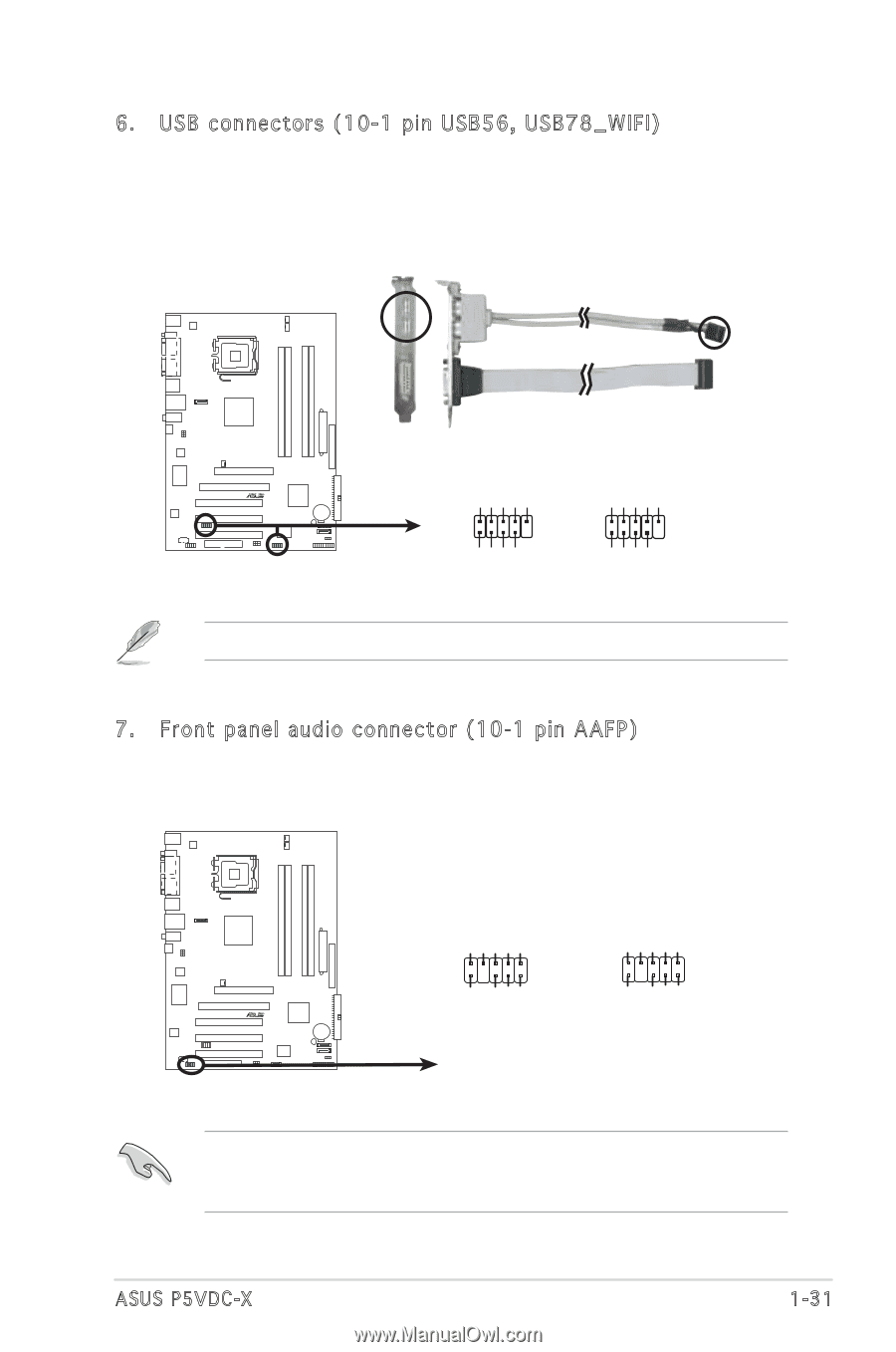
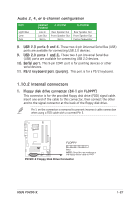
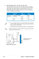
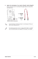
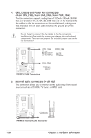
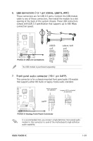
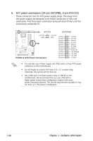
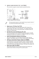
6. USB connectors (10-1 pin USB56, USB78_WIFI) These connectors are for USB 2.0 ports. Connect the USB module cable to any of these connectors, then install the module to a slot opening at the back of the system chassis. These USB connectors comply with USB 2.0 specification that supports up to 480 Mbps connection speed. Top:Line In Center:Line Out Below:Mic In P5VDC-X R USB56 1 P5VDC-X USB 2.0 Connectors USB+5V USB_P5USB_P5+ GND The USB module is purchased separately. USB+5V USB_P6USB_P6+ GND NC USB+5V USB_P7USB_P7+ GND USB+5V USB_P8USB_P8+ GND NC USB78_WIFI 1 7. Front panel audio connector (10-1 pin AAFP) This connector is for a chassis-mounted front panel audio I/O module that supports either HD Audio or legacy Azalia audio standard. Top:Line In Center:Line Out Below:Mic In P5VDC-X R Azalia-compliant pin definition Legacy AC'97-compliant pin definition Line out_L NC Line out_R MIC2_R MIC2_L PORT2 L SENSE_SEND PORT2 R PORT1 R PORT1 L AAFP NC NC NC AGND SENSE2_RETUR SENSE1_RETUR PRESENCE# GND P5VDC-X Analog Front Panel Connector It is recommended that you connect a high-definition front panel audio module to this connector to avail of the motherboardʼs high-definition audio capability. ASUS P5VDC-X Analog Front Panel Connector 1-31
-
 1
1 -
2
-
3
-
4
-
5
-
6
-
7
-
8
-
9
-
10
-
11
-
12
-
13
-
14
-
15
-
16
-
17
-
18
-
19
-
20
-
21
-
22
-
23
-
24
-
25
-
26
-
27
-
28
-
29
-
30
-
31
-
32
-
33
-
34
-
35
-
36
-
37
-
 38
38 -
 39
39 -
 40
40 -
 41
41 -
 42
42 -
 43
43 -
 44
44 -
 45
45 -
 46
46 -
 47
47 -
 48
48 -
49
-
50
-
51
-
52
-
53
-
54
-
55
-
56
-
57
-
58
-
59
-
60
-
61
-
62
-
63
-
64
-
65
-
66
-
67
-
68
-
69
-
70
-
71
-
72
-
73
-
74
-
75
-
76
-
77
-
78
-
79
-
80
-
81
-
82
-
83
-
84
-
85
-
86
-
87
-
88
-
89
-
90
-
91
-
92
 |
 |