Asus P5WD2 Motherboard Installation Guide - Page 53
Internal connectors - support disk
 |
View all Asus P5WD2 manuals
Add to My Manuals
Save this manual to your list of manuals |
Page 53 highlights
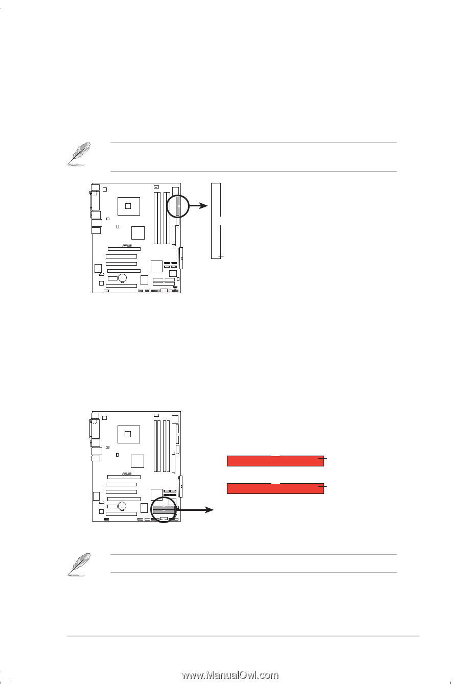
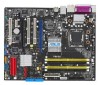
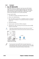
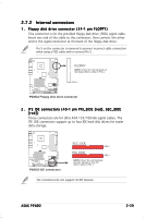
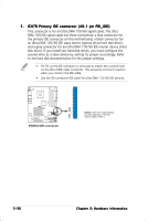
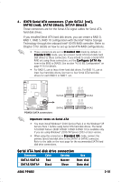
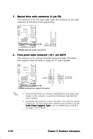
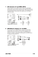
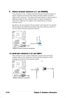
P5WD2 2.7.2 Internal connectors 1. Floppy disk drive connector (34-1 pin FLOPPY) This connector is for the provided floppy disk drive (FDD) signal cable. Insert one end of the cable to this connector, then connect the other end to the signal connector at the back of the floppy disk drive. Pin 5 on the connector is removed to prevent incorrect cable connection when using a FDD cable with a covered Pin 5. FLOPPY NOTE: Orient the red markings on the floppy ribbon cable to PIN 1. ® PIN 1 P5WD2 Floppy disk drive connector 2. ITE IDE connectors (40-1 pin PRI_EIDE [red], SEC_EIDE [red]) These connectors are for Ultra ATA 133/100/66 signal cables. The ITE IDE connectors support up to four IDE hard disk drives for easier data storage. ® P5WD2 IDE connectors P5WD2 SEC_EIDE PIN 1 PRI_EIDE PIN 1 NOTE: Orient the red markings (usually zigzag) on the IDE ribbon cable to PIN 1. The connectors do not support ATAPI devices. ASUS P5WD2 2-29
-
 1
1 -
2
-
3
-
4
-
5
-
6
-
7
-
8
-
9
-
10
-
11
-
12
-
13
-
14
-
15
-
16
-
17
-
18
-
19
-
20
-
21
-
22
-
23
-
24
-
25
-
26
-
27
-
28
-
29
-
30
-
31
-
32
-
33
-
34
-
35
-
36
-
37
-
38
-
39
-
40
-
41
-
42
-
43
-
44
-
45
-
46
-
47
-
 48
48 -
 49
49 -
 50
50 -
 51
51 -
 52
52 -
 53
53 -
 54
54 -
 55
55 -
 56
56 -
 57
57 -
 58
58 -
59
-
60
-
61
-
62
-
63
-
64
-
65
-
66
-
67
-
68
-
69
-
70
-
71
-
72
-
73
-
74
-
75
-
76
-
77
-
78
-
79
-
80
-
81
-
82
-
83
-
84
-
85
-
86
-
87
-
88
-
89
-
90
-
91
-
92
-
93
-
94
-
95
-
96
-
97
-
98
-
99
-
100
-
101
-
102
-
103
-
104
-
105
-
106
-
107
-
108
-
109
-
110
-
111
-
112
-
113
-
114
-
115
-
116
-
117
-
118
-
119
-
120
-
121
-
122
-
123
-
124
-
125
-
126
-
127
-
128
-
129
-
130
-
131
-
132
-
133
-
134
-
135
-
136
-
137
-
138
-
139
-
140
-
141
-
142
-
143
-
144
-
145
-
146
-
147
-
148
-
149
-
150
 |
 |