Asus P5WD2 Motherboard Installation Guide - Page 60
Atx12v, 4-pin Ez_plug
 |
View all Asus P5WD2 manuals
Add to My Manuals
Save this manual to your list of manuals |
Page 60 highlights
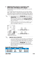
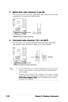
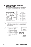
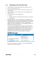
1 2 . ATX power connectors (24-pin EATXPWR, 2 x 4- p i n EATX12V, 4 - p i n E Z _ P L U G) These connectors are for ATX power supply plugs. The power supply plugs are designed to fit these connectors in only one orientation. Find the proper orientation and push down firmly until the connectors completely fit. +12V DC +12V DC +12V DC +12V DC P5WD2 EATX12V ® EZ_PLUG P5WD2 ATX power connectors GND GND GND GND EATXPWR +3 Volts +12 Volts +12 Volts +5V Standby Power OK Ground +5V EZ_DET GND +12V +5 Volts Ground +5 Volts Ground +3 Volts +3 Volts Ground +5 Volts +5 Volts +5 Volts -5 Volts Ground Ground Ground PSON# Ground -12 Volts +3 Volts When installing two VGA cards using a 20-pin ATX PSU with sufficient +12V capability, we recommend that you connect the EZ Plug for better current path from +12V. Refer to the PSU documentation for dual VGA power requirements. • You may use a 4-pin ATX12V power plug for this connector. • Make sure to remove the cap on the connector before connecting an 8-pin EPS +12V power plug. • Use only either a 4-pin ATX12V or an 8-pin EPS +12V power plug. Connecting other power plug types may cause serious damage to the system. 2x4-pin EATX12V Remove the cap before using an 8-pin power plug Connect a 4-pin power plug here 2-36 Chapter 2: Hardware information
-
 1
1 -
2
-
3
-
4
-
5
-
6
-
7
-
8
-
9
-
10
-
11
-
12
-
13
-
14
-
15
-
16
-
17
-
18
-
19
-
20
-
21
-
22
-
23
-
24
-
25
-
26
-
27
-
28
-
29
-
30
-
31
-
32
-
33
-
34
-
35
-
36
-
37
-
38
-
39
-
40
-
41
-
42
-
43
-
44
-
45
-
46
-
47
-
48
-
49
-
50
-
51
-
52
-
53
-
54
-
 55
55 -
 56
56 -
 57
57 -
 58
58 -
 59
59 -
 60
60 -
 61
61 -
 62
62 -
 63
63 -
 64
64 -
 65
65 -
66
-
67
-
68
-
69
-
70
-
71
-
72
-
73
-
74
-
75
-
76
-
77
-
78
-
79
-
80
-
81
-
82
-
83
-
84
-
85
-
86
-
87
-
88
-
89
-
90
-
91
-
92
-
93
-
94
-
95
-
96
-
97
-
98
-
99
-
100
-
101
-
102
-
103
-
104
-
105
-
106
-
107
-
108
-
109
-
110
-
111
-
112
-
113
-
114
-
115
-
116
-
117
-
118
-
119
-
120
-
121
-
122
-
123
-
124
-
125
-
126
-
127
-
128
-
129
-
130
-
131
-
132
-
133
-
134
-
135
-
136
-
137
-
138
-
139
-
140
-
141
-
142
-
143
-
144
-
145
-
146
-
147
-
148
-
149
-
150
 |
 |