Asus P65UP5 C-P55T2D User Manual - Page 13
Jumper Settings
 |
View all Asus P65UP5 C-P55T2D manuals
Add to My Manuals
Save this manual to your list of manuals |
Page 13 highlights
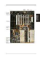
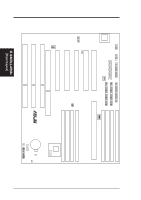
III. INSTALLATION (Jumpers) III. INSTALLATION Jumper Settings 1. On-Board Multi-I/O Selection (JP1) You can disable the onboard Multi-I/O (floppy, serial, parallel, and IrDA) individually through BIOS or entirely with the following jumper to use your own multi-I/O card. Multi-I/O Enable Disable JP1 [1-2] (Default) [2-3] JP1 1 2 3 Enable (Default) JP1 1 2 3 Disable R Multi I/O Setting 2. Flash ROM Boot Block Programming (JP4) This sets the operation mode of the boot block area of the BIOS Flash ROM to allow programming in the Prog (Program or enabled) position. Programming Protect (Disabled) Prog (Enabled) JP4 [1-2] (Default) [2-3] JP4 1 2 3 Protect (Default) JP4 1 2 3 Prog R Boot Block Programming ASUS P/I-P65UP5 User's Manual 13
-
 1
1 -
2
-
3
-
4
-
5
-
6
-
7
-
 8
8 -
 9
9 -
 10
10 -
 11
11 -
 12
12 -
 13
13 -
 14
14 -
 15
15 -
 16
16 -
 17
17 -
 18
18 -
19
-
20
-
21
-
22
-
23
-
24
-
25
-
26
-
27
-
28
-
29
-
30
-
31
-
32
 |
 |
ASUS P/I-P65UP5 User’s Manual
13
III. INSTALLATION
Jumper Settings
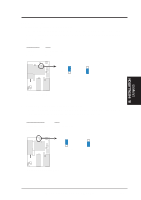
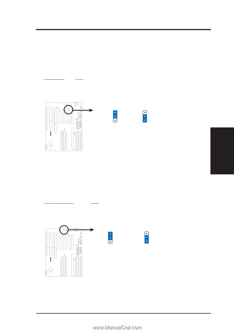
1.
On-Board Multi-I/O Selection (JP1)
You can disable the onboard Multi-I/O (floppy, serial, parallel, and IrDA) indi-
vidually through BIOS
or
entirely with the following jumper to use your own
multi-I/O card.
Multi-I/O
JP1
Enable
[1-2] (Default)
Disable
[2-3]
1
Multi I/O Setting
2
3
Enable (Default)
Disable
JP1
JP1
1
2
3
2.
Flash ROM Boot Block Programming (JP4)
This sets the operation mode of the boot block area of the BIOS Flash ROM to
allow programming in the
Prog
(
Prog
ram or enabled)
position.
Pr
ogramming
JP4
Protect (Disabled)
[1-2]
(Default)
Prog (Enabled)
[2-3]
Boot Block Programming
Protect (Default)
1
2
3
JP4
Prog
JP4
1
2
3
III.
INSTALLATION
(Jumpers)