Asus P65UP5 C-P55T2D User Manual - Page 19
CPU Card Slot
 |
View all Asus P65UP5 C-P55T2D manuals
Add to My Manuals
Save this manual to your list of manuals |
Page 19 highlights
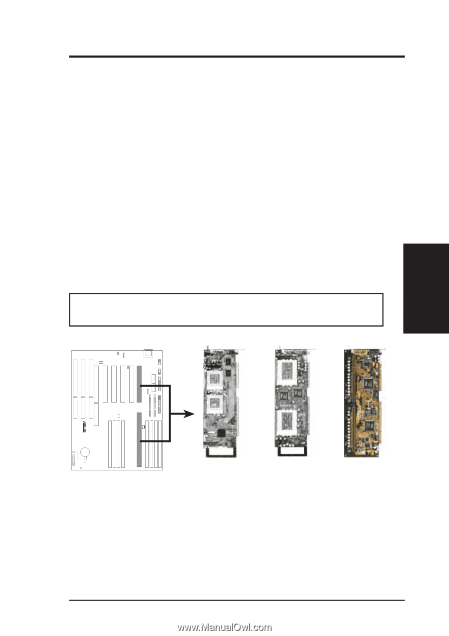
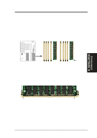
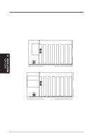
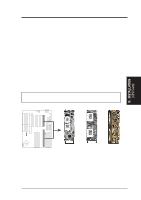
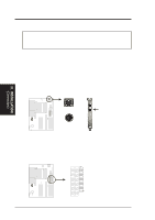
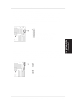
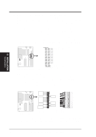
III. INSTALLATION One end of the CPU card has a bracket, which should slide into the system case front panel. Be sure that the system case can support a long PCI card on the first slot and that a groove is available for the bracket. Refer to your respective CPU card's documentation for details. General Installation Procedures for the ASUS CPU Card: 1. Remove the CPU card from its packaging without touching the integrated circuit (IC) chips, connectors, and other components. Place it onto the antistatic bag. 2. Follow instructions in the CPU card manual on installing the processor/s, support bracket, and setting jumpers. 3. Remove the expansion slot cover for the first slot. 4. Carefully align the CPU card over the CPU Card Slot (CPU SLOT A and CPU SLOT B). 5. Be sure that the card is perpendicular to the baseboard. Firmly press one end of the card halfway in, the other end halfway in, then the first end completely in, and finally, the second end completely in. Be sure that all the connectors are evenly inserted into the slots. 6. Screw in the metal bracket to the system case. WARNING! Move the system carefully and only with the power off because the CPU card is heavy as well as delicate. III. INSTALLATION (CPU Card) R CPU Card Slot C-P55T2D C-P6ND C-PKND NOTE: The BIOS on the CPU cards are different. When adding a CPU card, find the BIOS chip that came with the CPU card and replace it with the one on the baseboard, if one is present. ASUS P/I-P65UP5 User's Manual 19
-
 1
1 -
2
-
3
-
4
-
5
-
6
-
7
-
8
-
9
-
10
-
11
-
12
-
13
-
 14
14 -
 15
15 -
 16
16 -
 17
17 -
 18
18 -
 19
19 -
 20
20 -
 21
21 -
 22
22 -
 23
23 -
 24
24 -
25
-
26
-
27
-
28
-
29
-
30
-
31
-
32
 |
 |