Asus P65UP5 C-P55T2D User Manual - Page 26
Turbo LED Switch TB LED
 |
View all Asus P65UP5 C-P55T2D manuals
Add to My Manuals
Save this manual to your list of manuals |
Page 26 highlights
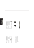
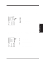
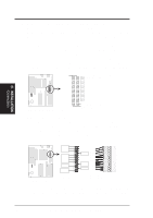
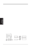
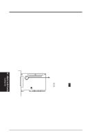
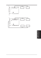
III. INSTALLATION 9. Turbo LED Switch (TB LED) The baseboard's turbo function is always on. The turbo LED connection is labeled here but the LED will remain constantly lit while the system power is on. You may wish to connect the Power LED from the system case to this lead. 10. SMI Suspend Switch Lead (SMI) This allows the user to manually place the system into a suspend mode or "Green" mode where system activity will be instantly decreased to save electricity and expand the life of certain components when the system is not in use. This 2-pin connector connects to the case-mounted suspend switch. If the switch is not available, you can use the turbo switch. SMI is activated when it detects a short to open moment; leaving it shorted, therefore, will not cause any problems. This may require one or two presses depending on the switch's position. Wake-up can be controlled through the BIOS but the keyboard will always wake up (the SMI lead cannot wake up) the system. If you want to use this connector, the "Suspend Mode" under Power Management Setup of the BIOS SOFTWARE must be set to Enable. 11. Reset Switch Lead (RESET) This 2-pin connector connects to the case-mounted reset switch to allow the restarting of your computer without having to turn off it off. This is a preferred method of restarting to prolong the life of the system's power supply. 12. System Power LED (KEYLOCK) This 3-pin connector connects the system power LED, which lights when the system is powered on and blinks when it is in sleep mode. 13. Keyboard Lock Switch Lead (KEYLOCK) This 2-pin connector connects to the case-mounted key switch to allow keyboard locking. 14. Speaker Connector (SPEAKER) This 4-pin connector connects to the case-mounted speaker. R III. INSTALLATION (Connectors) Turbo or Power LED +5V GND SMI Lead GND Reset SW GND System Panel Connectors +5V NC Power LED GND LOCK GND Keyboard Lock +5V GND Speaker GND Connector SPKR 26 ASUS P/I-P65UP5 User's Manual
-
 1
1 -
2
-
3
-
4
-
5
-
6
-
7
-
8
-
9
-
10
-
11
-
12
-
13
-
14
-
15
-
16
-
17
-
18
-
19
-
20
-
 21
21 -
 22
22 -
 23
23 -
 24
24 -
 25
25 -
 26
26 -
 27
27 -
 28
28 -
 29
29 -
 30
30 -
 31
31 -
32
 |
 |
