Asus P65UP5 C-P55T2D User Manual - Page 27
Power Supply, CPU Fan Connectors FANPWR1, FANPWR2, FANPWR3
 |
View all Asus P65UP5 C-P55T2D manuals
Add to My Manuals
Save this manual to your list of manuals |
Page 27 highlights
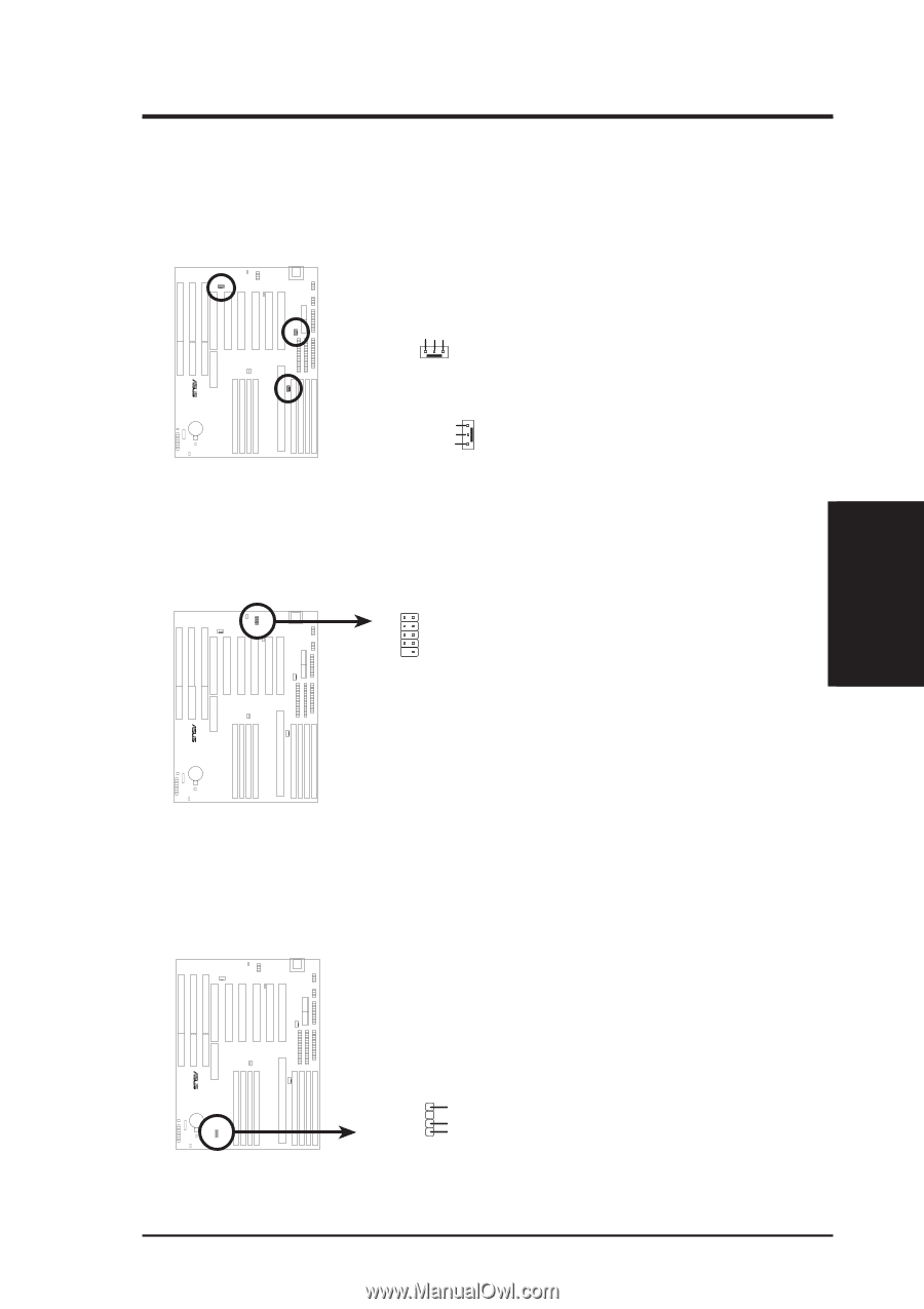
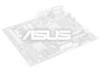
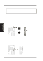
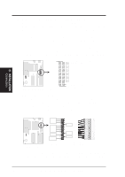
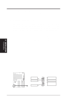
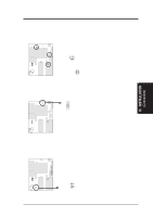
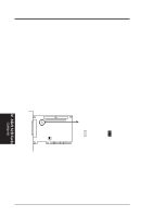
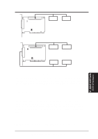
III. INSTALLATION 15. Power Supply, CPU Fan Connectors (FANPWR1, FANPWR2, FANPWR3) This connector supports a 3-pin CPU cooling fan of 500Amp (6watts) or less with a minimum of 3,500RPM. Depending on the fan manufacturer, the wiring and plug may be different. The red wire should be positive and the black wire should be ground. Power Supply Fan Ground +12 Volts (NC) III. INSTALLATION (Connectors) R R R CPU Fan Power (2) (NC) +12 Volts Ground Power Supply, CPU Fan Power 16. USB Module Connector (USB) If you want to use the universal serial bus (USB), you need to purchase an external connector set. The external connector connects to the 9-pin block. 12 9 10 1: USB +5Volt 2: USB +5Volt 3: USB Port 1 - 4: USB Port 0 - 5: USB Port 1 + 6: USB Port 0 + 7: Ground 8: Ground 9: (no connection) 10: (no connection) USB Module Connector 17. Chassis Open Alarm Connector (CHASSIS) (with optional LM78) This lead is for an open chassis monitor. A high level signal to the chassis signal lead will indicate to the system that the chassis has been opened. For the chassis open alarm feature to work, you must have the LM78 hardware monitor (optional) onboard and connect a sensor or switch to the connector. The +5V power comes from the power supply, when the A/C is connected. With the A/C power disconnected, the +3V power comes from the onboard button cell battery. Chassis Connector (optional) Power (+3V/+5V) Chassis Signal Ground ASUS P/I-P65UP5 User's Manual 27
-
 1
1 -
2
-
3
-
4
-
5
-
6
-
7
-
8
-
9
-
10
-
11
-
12
-
13
-
14
-
15
-
16
-
17
-
18
-
19
-
20
-
21
-
 22
22 -
 23
23 -
 24
24 -
 25
25 -
 26
26 -
 27
27 -
 28
28 -
 29
29 -
 30
30 -
 31
31 -
 32
32
 |
 |