Asus P7H55-M LX User Manual - Page 11
Motherboard overview - intel motherboard
 |
View all Asus P7H55-M LX manuals
Add to My Manuals
Save this manual to your list of manuals |
Page 11 highlights
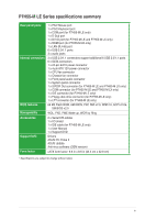
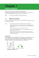
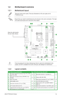
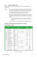
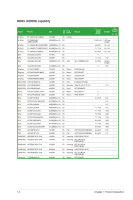
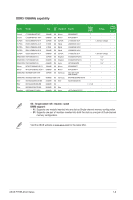
1.2 1.2.1 Motherboard overview Motherboard layout The layout varies with models. The layout illustrations in this user guide are for P7H55-M LE only. Ensure that you install the motherboard into the chassis in the correct orientation. The edge with external ports goes to the rear part of the chassis. KBMS 12 3 21.8cm(8.6in) 4 56 COM2 COM1 Place this side towards the rear of the chassis. HDMI ATX12V Super LPT I/O 7 DDR3 DIMM_A1 (64bit, 240-pin module) DDR3 DIMM_B1 (64bit, 240-pin module) PRI_EIDE EATXPWR 24.4cm(9.6in) DVI VGA LGA1156 USB3_6 FLOPPY LAN1_USB12 CHA_FAN AUDIO RTL 8112L VIA VT1708S AAFP CPU_FAN ICS 954 A4 Lithium Cell CMOS Power PCIEX16 P7H55-M LE PCI1 PCI2 PCIEX4_1 SPDIF_OUT USB1112 USB910 Intel® H55 64Mb BIOS SATA1 SATA2 SATA3 SATA4 USB78 CLRTC SATA5 SATA6 SB_PWR F_PANEL 2 8 9 10 15 14 13 12 11 Place six screws into the holes indicated by circles to secure the motherboard to the chassis. DO NOT overtighten the screws! Doing so can damage the motherboard. 1.2.2 Layout contents Connectors/Jumpers/Slots/LED 1. CPU and Chassis fan connectors (4-pin CPU_FAN, 3-pin CHA_FAN) 2. ATX power connectors (24-pin EATXPWR, 4-pin ATX12V) 3. Intel® CPU socket 4. DDR3 DIMM sockets 5. Serial port connectors (10-1 pin COM2) 6. LPT connector (26-1 pin LPT) 7. Floppy disk drive connector (34-1 pin FLOPPY) 8. IDE connector (40-1 pin PRI_EIDE) Page Connectors/Jumpers/Slots/LED 1-12 9. Serial ATA connectors (7-pin SATA1-6) 1-13 10. Onboard LED (SB_PWR) 11. System panel connector (10-1 pin F_PANEL) 1-3 12. Clear RTC RAM (3-pin CLRTC) 1-15 13. USB connectors (10-1 pin USB78, USB910, USB1112) 1-15 14. Digital audio connector (4-1 pin SPDIF_OUT) 1-14 15. Front panel audio connector (10-1 pin AAFP) 1-16 Page 1-11 1-1 1-12 1-8 1-10 1-11 1-14 ASUS P7H55-M LE Series 1-2
-
 1
1 -
2
-
3
-
4
-
5
-
 6
6 -
 7
7 -
 8
8 -
 9
9 -
 10
10 -
 11
11 -
 12
12 -
 13
13 -
 14
14 -
 15
15 -
 16
16 -
17
-
18
-
19
-
20
-
21
-
22
-
23
-
24
-
25
-
26
-
27
-
28
-
29
-
30
-
31
-
32
-
33
-
34
-
35
-
36
-
37
-
38
-
39
-
40
-
41
-
42
-
43
-
44
-
45
-
46
-
47
-
48
-
49
 |
 |
