Asus P7H55-M LX User Manual - Page 19
Internal connectors - motherboard specifications
 |
View all Asus P7H55-M LX manuals
Add to My Manuals
Save this manual to your list of manuals |
Page 19 highlights
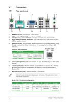
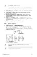
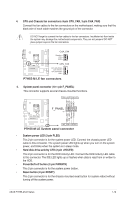
To configure an 8-channel audio output: Use a chassis with HD audio module in the front panel to support an 8-channel audio output. 8. USB 2.0 ports 1 and 2. These two 4-pin Universal Serial Bus (USB) ports connect to USB 2.0/1.1 devices. 9. USB 2.0 ports 3, 4, 5, and 6. These four 4-pin Universal Serial Bus (USB) ports connect to USB 2.0/1.1 devices. 10. DVI-D port (for P7H55-M LE and P7H55-M LX only). This port is for any DVI-D compatible device. DVI-D can't be converted to output RGB Signal to CRT and isn't compatible with DVI-I. 11. HDMI port (for P7H55-M LE only). This is a High-Definition Mulltimedia Interface (HDMI) connector, and is HDCP compliant allowing playback of HD DVD, Blu-Ray, and other protected content. 12. PS/2 Keyboard port. This port is for a PS/2 keyboard. 1.7.2 Internal connectors 1. USB connectors (10-1 pin USB78, USB910, USB1112) These connectors are for USB 2.0 ports. Connect the USB module cable to any of these connectors, then install the module to a slot opening at the back of the system chassis. These USB connectors comply with the USB 2.0 specification that supports up to 480Mbps connection speed. USB1112 USB910 USB78 USB+5V USB_P12USB_P12+ GND NC USB+5V USB_P10USB_P10+ GND NC USB+5V USB_P8USB_P8+ GND NC P7H55-M LE PIN 1 PIN 1 PIN 1 USB+5V USB_P11USB_P11+ GND USB+5V USB_P9USB_P9+ GND USB+5V USB_P7USB_P7+ GND P7H55-M LE USB2.0 connectors Never connect a 1394 cable to the USB connectors. Doing so will damage the motherboard! The USB 2.0 module is purchased separately. ASUS P7H55-M LE Series 1-10
-
 1
1 -
2
-
3
-
4
-
5
-
6
-
7
-
8
-
9
-
10
-
11
-
12
-
13
-
 14
14 -
 15
15 -
 16
16 -
 17
17 -
 18
18 -
 19
19 -
 20
20 -
 21
21 -
 22
22 -
 23
23 -
 24
24 -
25
-
26
-
27
-
28
-
29
-
30
-
31
-
32
-
33
-
34
-
35
-
36
-
37
-
38
-
39
-
40
-
41
-
42
-
43
-
44
-
45
-
46
-
47
-
48
-
49
 |
 |
