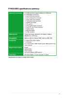
Asus P7H55 USB3 User Guide - Page 14
Motherboard overview - intel h55
 |
View all Asus P7H55 USB3 manuals
Add to My Manuals
Save this manual to your list of manuals |
Page 14 highlights
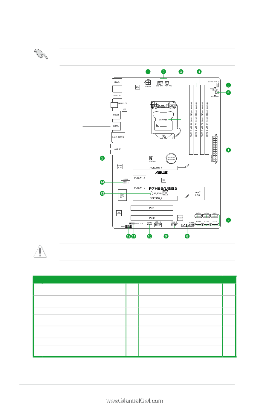
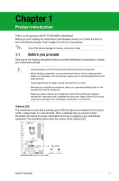
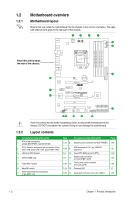
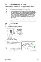
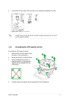
1.2 1.2.1 Motherboard overview Motherboard layout Ensure that you install the motherboard into the chassis in the correct orientation. The edge with external ports goes to the rear part of the chassis. Place this side towards the rear of the chassis. Place six screws into the holes indicated by circles to secure the motherboard to the chassis. DO NOT overtighten the screws! Doing so can damage the motherboard. 1.2.2 Layout contents Connectors/Jumpers/Slots/LED 1. ATX power connectors (24-pin EATXPWR, 4-pin EATX12V) 2. CPU, chassis, and power fan connectors (4-pin CPU_FAN, 3-pin CHA_FAN, 3-pin PWR_FAN) 3. LGA1156 CPU Socket 4. DDR3 DIMM slots 5. Turbo Key II switch 6. MemOK! switch 7. Intel® H55 Serial ATA connectors (7-pin SATA 1-6) Page Connectors/Jumpers/Slots/LED Page 1-22 8. System panel connector (20-8 pin PANEL) 1-26 1-23 9. USB connectors (10-1 pin USB910, USB1112) 1-27 1-3 10. Clear RTC RAM (3-pin CLRTC) 1-18 1-8 11. Digital audio connector (4-1 pin SPDIF_OUT) 1-23 1-20 12. Front panel audio connector (10-1 pin AAFP) 1-24 1-19 13. Onboard LED 1-1 1-25 14. Serial port connector (10-1 pin COM1) 1-24 1-2 Chapter 1: Product introduction
-
 1
1 -
2
-
3
-
4
-
5
-
6
-
7
-
8
-
 9
9 -
 10
10 -
 11
11 -
 12
12 -
 13
13 -
 14
14 -
 15
15 -
 16
16 -
 17
17 -
 18
18 -
 19
19 -
20
-
21
-
22
-
23
-
24
-
25
-
26
-
27
-
28
-
29
-
30
-
31
-
32
-
33
-
34
-
35
-
36
-
37
-
38
-
39
-
40
-
41
-
42
-
43
-
44
-
45
-
46
-
47
-
48
-
49
-
50
-
51
-
52
-
53
-
54
-
55
-
56
-
57
-
58
-
59
-
60
-
61
-
62
-
63
-
64
-
65
-
66
-
67
-
68
-
69
-
70
 |
 |