Asus P8B75-M P8B75-M User's Manual - Page 17
Motherboard layout, Layout contents
 |
View all Asus P8B75-M manuals
Add to My Manuals
Save this manual to your list of manuals |
Page 17 highlights
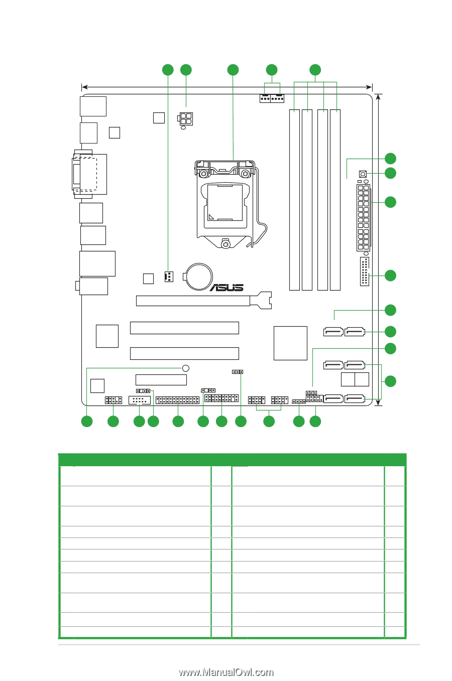
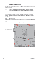
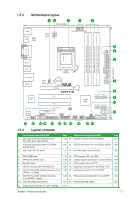
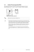
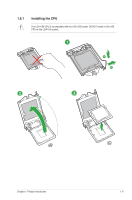
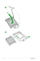
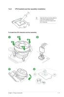
1.5.3 Motherboard layout 12 3 1 4 22.6cm(8.9in) KBMS HDMI ASM 1442 ATX12V EPU CHA_FAN2 CPU_FAN DVI_VGA LGA1155 USB34 USB3_12 5 MemOK! 6 DRAM_LED 2 DDR3 DIMM_A1 (64bit, 240-pin module) DDR3 DIMM_A2 (64bit, 240-pin module) DDR3 DIMM_B1 (64bit, 240-pin module) DDR3 DIMM_B2 (64bit, 240-pin module) 24.4cm(9.6in) EATXPWR USB3_34 LAN_USB12 AUDIO RTL 8111F CHA_FAN1 Lithium Cell CMOS Power PCIEX16 Super I/O P8B75-M PCI1 PCI2 SB_PWR DIS_ME Intel® B75 SATA3G_1 SATA6G_1 SATA3G_3 SATA3G_2 VIA VT1708S AAFP PCIEX4_1 SPDIF_OUT COM1 LPT CHASSIS 64Mb 64Mb BIOS BIOS TPM USB78 USB56 CLRTC SATA3G_5 SATA3G_4 SPEAKER F_PANEL 7 8 9 10 8 21 20 19 18 17 16 15 14 13 12 11 1.5.4 Layout contents Connectors/Jumpers/Slots/LED 1. CPU and chassis fan connectors (4-pin CPU_FAN, 3-pin CHA_FAN1/2) 2. ATX power connectors (24-pin EATXPWR, 4-pin ATX12V) 3. Intel® LGA1155 CPU socket Page Connectors/Jumpers/Slots/LED 1-26 12. Speaker connector (4-pin SPEAKER) Page 1-27 1-25 13. USB 2.0 connectors (10-1 pin USB56, USB78) 1-29 1-3 14. Intel® ME jumper (3-pin DIS_ME) 1-20 4. DDR3 DIMM slots 1-13 15. TPM connector (20-1 pin TPM) 1-30 5. DRAM LED (DRAM_LED) 1-32 16. Chassis intrusion connector (4-1 pin CHASSIS) 1-25 6. MemOK! switch 1-31 17. LPT connector (26-1 pin LPT) 1-26 7. USB 3.0 connector (20-1 pin USB3_34) 1-29 18. Digital audio connector (4-1 pin SPDIF_OUT) 1-24 8. Intel® B75 Serial ATA 3.0Gb/s connectors (7-pin 1-28 19. Serial port connector (10-1 pin COM1) 1-30 SATA3G_1~5 [blue]) 9. Intel® B75 Serial ATA 6.0Gb/s connectors (7-pin SATA6G_1 [gray]) 1-28 20. Front panel audio connector (10-1 pin AAFP) 1-24 10. Clear RTC RAM (3-pin CLRTC) 1-21 21. Onboard LED (SB_PWR) 1-32 11. System panel connector (10-1 pin F_PANEL) 1-27 Chapter 1: Product introduction 1-7
-
 1
1 -
2
-
3
-
4
-
5
-
6
-
7
-
8
-
9
-
10
-
11
-
 12
12 -
 13
13 -
 14
14 -
 15
15 -
 16
16 -
 17
17 -
 18
18 -
 19
19 -
 20
20 -
 21
21 -
 22
22 -
23
-
24
-
25
-
26
-
27
-
28
-
29
-
30
-
31
-
32
-
33
-
34
-
35
-
36
-
37
-
38
-
39
-
40
-
41
-
42
-
43
-
44
-
45
-
46
-
47
-
48
-
49
-
50
-
51
-
52
-
53
-
54
-
55
-
56
-
57
-
58
-
59
-
60
-
61
-
62
-
63
-
64
-
65
-
66
-
67
-
68
-
69
-
70
-
71
-
72
-
73
-
74
-
75
-
76
 |
 |