Asus P8B75-M P8B75-M User's Manual - Page 39
P8B75-M USB2.0 connector
 |
View all Asus P8B75-M manuals
Add to My Manuals
Save this manual to your list of manuals |
Page 39 highlights
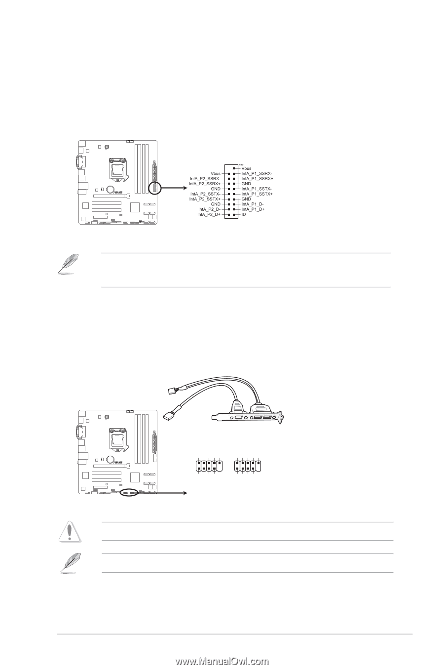
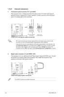
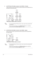
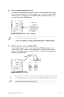
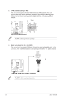
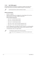
11. USB 3.0 connector (20-1 pin USB3_34) This connector is for the additional USB 3.0 ports. Connect the USB 3.0 bracket cable to this connector, then install the USB 3.0 bracket to the rear side of the chassis. If your chassis support customized front panel installation, with ASUS USB 3.0 header, you can have a front panel USB 3.0 solution. USB3_34 P8B75-M P8B75-M USB3.0 Front panel connector • The USB 3.0 module is purchased separately. • Due to Intel® limitations, the USB3_34 only supports Windows® 7 operating system. 12. USB 2.0 connectors (10-1 pin USB56, USB78) These connectors are for USB 2.0 ports. Connect the USB module cable to any of these connectors, then install the module to a slot opening at the back of the system chassis. These USB connectors comply with USB 2.0 specification that supports up to 480 Mbps connection speed. USB78 USB56 USB+5V USB_P8USB_P8+ GND NC USB+5V USB_P6USB_P6+ GND NC PIN 1 USB+5V USB_P7USB_P7+ GND PIN 1 USB+5V USB_P5USB_P5+ GND P8B75-M P8B75-M USB2.0 connector Never connect a 1394 cable to the USB connectors. Doing so will damage the motherboard! The USB module cable is purchased separately. Chapter 1: Product introduction 1-29
-
 1
1 -
2
-
3
-
4
-
5
-
6
-
7
-
8
-
9
-
10
-
11
-
12
-
13
-
14
-
15
-
16
-
17
-
18
-
19
-
20
-
21
-
22
-
23
-
24
-
25
-
26
-
27
-
28
-
29
-
30
-
31
-
32
-
33
-
 34
34 -
 35
35 -
 36
36 -
 37
37 -
 38
38 -
 39
39 -
 40
40 -
 41
41 -
 42
42 -
 43
43 -
 44
44 -
45
-
46
-
47
-
48
-
49
-
50
-
51
-
52
-
53
-
54
-
55
-
56
-
57
-
58
-
59
-
60
-
61
-
62
-
63
-
64
-
65
-
66
-
67
-
68
-
69
-
70
-
71
-
72
-
73
-
74
-
75
-
76
 |
 |