Asus P8H67-M2 SI User Manual - Page 12
Motherboard overview - tpm si intel h67
 |
View all Asus P8H67-M2 SI manuals
Add to My Manuals
Save this manual to your list of manuals |
Page 12 highlights
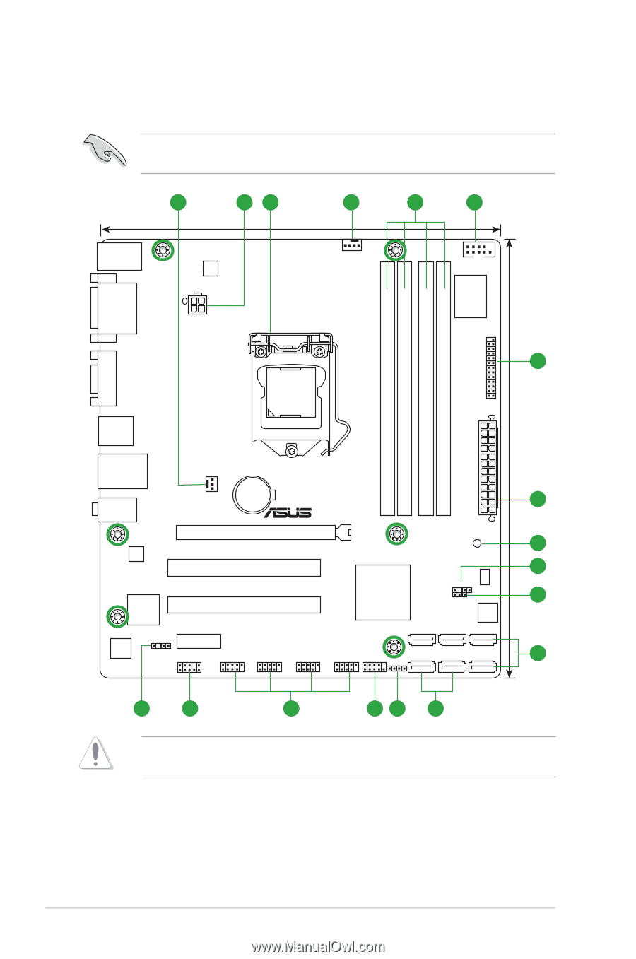
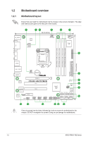
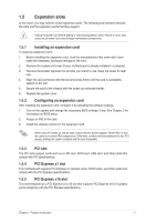
1.2 1.2.1 Motherboard overview Motherboard layout Ensure that you install the motherboard into the chassis in the correct orientation. The edge with external ports goes to the rear part of the chassis. 1 23 1 4 5 22.4cm(8.8in) DVI KB_USB56 EPU ATX12V CPU_FAN COM1 Super I/O LPT 6 DDR3 DIMM_A1 (64bit, 240-pin module) DDR3 DIMM_A2 (64bit, 240-pin module) DDR3 DIMM_B1 (64bit, 240-pin module) DDR3 DIMM_B2 (64bit, 240-pin module) VGA LGA1155 24.4cm(9.6in) USB34 EATXPWR LAN1_USB12 Lithium Cell CHA_FAN CMOS Power 2 AUDIO PCIEX16 RTL 8111E P8H67-M2/TPM/SI PCI1 7 SB_PWR 8 TPM IC asmedia ASM1083 PCI2 VIA VT1708S SPDIF_OUT PCIEX1_1 AAFP USB1314 USB1112 USB910 Intel® H67 CHASSIS CLRTC 32Mb BIOS SATA3G_3 SATA3G_1 SATA6G_1 USB78 F_PANEL SATA3G_4 SATA3G_2 SATA6G_2 SPEAKER 9 10 16 15 14 13 12 11 Place six screws into the holes indicated by circles to secure the motherboard to the chassis. DO NOT overtighten the screws! Doing so can damage the motherboard. 1-2 ASUS P8H67-M2 Series
-
 1
1 -
2
-
3
-
4
-
5
-
6
-
 7
7 -
 8
8 -
 9
9 -
 10
10 -
 11
11 -
 12
12 -
 13
13 -
 14
14 -
 15
15 -
 16
16 -
 17
17 -
18
-
19
-
20
-
21
-
22
-
23
-
24
-
25
-
26
-
27
-
28
-
29
-
30
-
31
-
32
-
33
-
34
-
35
-
36
-
37
-
38
-
39
-
40
-
41
-
42
-
43
-
44
-
45
-
46
-
47
-
48
-
49
-
50
-
51
-
52
-
53
-
54
-
55
-
56
 |
 |