Asus P8H67-M2 SI User Manual - Page 24
P8H67-M2/TPM/SI Intel, SATA 3.0Gb/s connectors
 |
View all Asus P8H67-M2 SI manuals
Add to My Manuals
Save this manual to your list of manuals |
Page 24 highlights
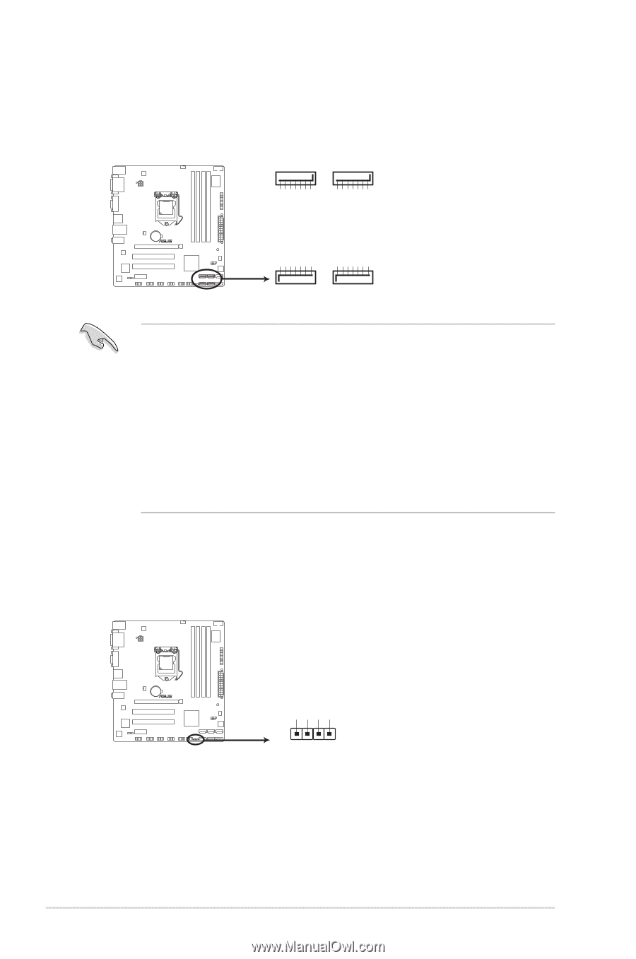
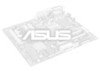
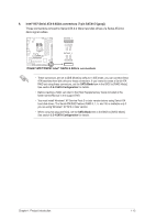
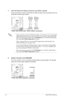
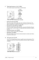
7. Intel® H67 Serial ATA 3.0Gb/s connectors (7-pin SATA1~4 [blue]) These connectors connect to Serial ATA 3.0 Gb/s hard disk drives and optical drives via Serial ATA 3.0 Gb/s signal cables. SATA3G_3 SATA3G_1 GND RSATA_TXP1 RSATA_TXN1 GND RSATA_RXP1 RSATA_RXN1 GND GND RSATA_TXP3 RSATA_TXN3 GND RSATA_RXP3 RSATA_RXN3 GND GND RSATA_RXN2 RSATA_RXP2 GND RSATA_TXN2 RSATA_TXP2 GND GND RSATA_RXN4 RSATA_RXP4 GND RSATA_TXN4 RSATA_TXP4 GND P8H67-M2/TPM/SI SATA3G_4 SATA3G_2 P8H67-M2/TPM/SI Intel® SATA 3.0Gb/s connectors • These connectors are set to [IDE Mode] by default. In IDE mode, you can connect Serial ATA boot/data hard disk drives to these connectors. If you intend to create a Serial ATA RAID set using these connectors, set the SATA Mode item in the BIOS to [RAID Mode]. See section 2.5.4 SATA Configuration for details. • Before creating a RAID set, refer to the RAID Supplementary Guide included in the folder named Manual in the support DVD. • You must install Windows® XP Service Pack 3 or later version before using Serial ATA hard disk drives. The Serial ATA RAID feature (RAID 0, 1, 5, and 10) is available only if you are using Windows® XP SP3 or later version. • When using hot-plug and NCQ, set the SATA Mode item in the BIOS to [AHCI Mode]. See section 2.5.4 SATA Configuration for details. 8. Speaker connector (4-pin SPEAKER) The 4-pin connector is for the chassis-mounted system warning speaker. The speaker allows you to hear system beeps and warnings. SPEAKER +5V GND GND Speaker Out P8H67-M2/TPM/SI PIN 1 P8H67-M2/TPM/SI Speaker connector 1-14 ASUS P8H67-M2 Series
-
 1
1 -
2
-
3
-
4
-
5
-
6
-
7
-
8
-
9
-
10
-
11
-
12
-
13
-
14
-
15
-
16
-
17
-
18
-
 19
19 -
 20
20 -
 21
21 -
 22
22 -
 23
23 -
 24
24 -
 25
25 -
 26
26 -
 27
27 -
 28
28 -
 29
29 -
30
-
31
-
32
-
33
-
34
-
35
-
36
-
37
-
38
-
39
-
40
-
41
-
42
-
43
-
44
-
45
-
46
-
47
-
48
-
49
-
50
-
51
-
52
-
53
-
54
-
55
-
56
 |
 |