Asus P8H67 User Manual - Page 40
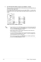
CPU, Chassis, and Power fan connectors 4-pin CPU_FAN, 3-pin PWR_FAN, 4-pin, CHA_FAN1 and CHA_FAN2,
 |
View all Asus P8H67 manuals
Add to My Manuals
Save this manual to your list of manuals |
Page 40 highlights
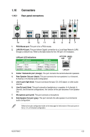
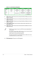
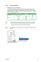
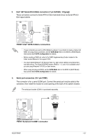
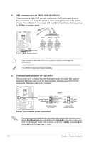
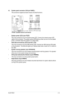
Rotation +12V GND CPU FAN PWM CPU FAN IN CPU FAN PWR GND GND CPU FAN PWR CPU FAN IN CPU FAN PWM 5. CPU, Chassis, and Power fan connectors (4-pin CPU_FAN, 3-pin PWR_FAN, 4-pin CHA_FAN1 and CHA_FAN2) Connect the fan cables to the fan connectors on the motherboard, making sure that the black wire of each cable matches the ground pin of the connector. DO NOT forget to connect the fan cables to the fan connectors. Insufficient air flow inside the system may damage the motherboard components. They are not jumpers! DO NOT place jumper caps on the fan connectors. CPU_FAN PWR_FAN CHA_FAN1 CHA_FAN2 P8H67 P8H67 fan connectors • The CPU_FAN connector supports a CPU fan of maximum 2A (24 W) fan power. • Only the CPU_FAN, CHA_FAN1 and CHA_FAN2 connectors support the ASUS Fan Xpert feature. • If you install two VGA cards, we recommend that you plug the rear chassis fan cable to the motherboard connector labeled CHA_FAN1 or CAH_FAN 2 for better thermal environment. 6. Digital audio connector (4-1 pin SPDIF_OUT) This connector is for an additional Sony/Philips Digital Interface (S/PDIF) port. CPU FAN PWM CPU FAN IN CPU FAN PWR GND +5V SPDIFOUT GND P8H67 SPDIF_OUT P8H67 Digital audio connector The S/PDIF module is purchased separately. 1-28 Chapter 1: Product introduction
-
 1
1 -
2
-
3
-
4
-
5
-
6
-
7
-
8
-
9
-
10
-
11
-
12
-
13
-
14
-
15
-
16
-
17
-
18
-
19
-
20
-
21
-
22
-
23
-
24
-
25
-
26
-
27
-
28
-
29
-
30
-
31
-
32
-
33
-
34
-
 35
35 -
 36
36 -
 37
37 -
 38
38 -
 39
39 -
 40
40 -
 41
41 -
 42
42 -
 43
43 -
 44
44 -
 45
45 -
46
-
47
-
48
-
49
-
50
-
51
-
52
-
53
-
54
-
55
-
56
-
57
-
58
-
59
-
60
-
61
-
62
-
63
-
64
-
65
-
66
-
67
-
68
-
69
-
70
-
71
-
72
-
73
-
74
-
75
-
76
-
77
-
78
-
79
-
80
 |
 |
