Asus RS100-X5 User Manual - Page 56
LAN1 link activity LED 2-pin LAN1_LINKACTLED
 |
UPC - 610839660971
View all Asus RS100-X5 manuals
Add to My Manuals
Save this manual to your list of manuals |
Page 56 highlights
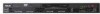
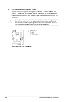
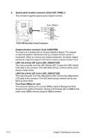
6. System panel auxiliary connector (20-pin AUX_PANEL1) This connector supports several server system functions. AUX_PANEL1 P5GC-MR R LAN2_LINKACTLED+ LAN2_LINKACTLEDLAN1_LINKACTLEDLAN1_LINKACTLED+ +5VSB I2CDATA_P2 GND I2CCLK_P2 NC GND GND CASEOPEN +5VSB 1 P5GC-MR.Auxiliary.Panel.Connector • Chassis Intrusion connector (3-pin CASEOPEN) This lead is for a chassis with an intrusion detection feature. This requires an external detection mechanism such as a chassis intrusion sensor or microswitch. When you remove any chassis component, the sensor triggers and sends a high-level signal to this lead to record a chassis intrusion event. • LAN1 link activity LED (2-pin LAN1_LINKACTLED) This 2-pin connector is for the LAN1 Activity LED. Connect the LAN1 Activity LED cable to this connector. This LED blinks during a network activity and is always lit when linked. • LAN2 link activity LED (2-pin LAN2_LINKACTLED) This 2-pin connector is for the LAN2 Activity LED. Connect the LAN2 Activity LED cable to this connector. This LED blinks during a network activity and lights up when linked. • Front Panel SMBus (6-1 pin) This connector allows you to connect SMBus (System Management Bus) devices to the system front panel. Devices communicate with an SMBus host and/or other SMBus devices using the SMBus interface. 4-10 Chapter 4: Motherboard Information
-
 1
1 -
2
-
3
-
4
-
5
-
6
-
7
-
8
-
9
-
10
-
11
-
12
-
13
-
14
-
15
-
16
-
17
-
18
-
19
-
20
-
21
-
22
-
23
-
24
-
25
-
26
-
27
-
28
-
29
-
30
-
31
-
32
-
33
-
34
-
35
-
36
-
37
-
38
-
39
-
40
-
41
-
42
-
43
-
44
-
45
-
46
-
47
-
48
-
49
-
50
-
 51
51 -
 52
52 -
 53
53 -
 54
54 -
 55
55 -
 56
56 -
 57
57 -
 58
58 -
 59
59 -
 60
60 -
 61
61 -
62
-
63
-
64
-
65
-
66
-
67
-
68
-
69
-
70
-
71
-
72
-
73
-
74
-
75
-
76
-
77
-
78
-
79
-
80
-
81
-
82
-
83
-
84
-
85
-
86
-
87
-
88
-
89
-
90
-
91
-
92
-
93
-
94
-
95
-
96
-
97
-
98
 |
 |
