Asus RS260-E3 RS8 RS260-E3 - Page 75
Connectors
 |
View all Asus RS260-E3 RS8 manuals
Add to My Manuals
Save this manual to your list of manuals |
Page 75 highlights
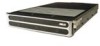
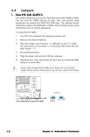
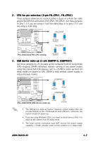
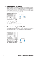
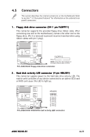
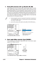
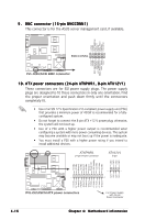
4.5 Connectors This section describes the internal connectors on the motherboard. Refer to section "1.4 Rear panel features" for information on the external (rear panel) connectors. 1. Floppy disk drive connector (34-1 pin FLOPPY1) This connector supports the provided floppy drive ribbon cable. After connecting one end to the motherboard, connect the other end to the floppy drive. (Pin 5 is removed to prevent incorrect insertion when using ribbon cables with pin 5 plug). PVL-D/2U/SCSI ® FLOPPY1 PIN 1 NOTE: Orient the red markings on the floppy ribbon cable to PIN 1. PVL-D/2U/SCSI Floppy disk drive connector 2. Hard disk activity LED connector (4-pin HDLED1) This connector supplies power to the hard disk drive activity LED. The read or write activities of any device connected to an add-on SCSI card or RAID card cause this LED to light up. HDLED1 1 PVL-D/2U/SCSI SCSI/SATA card activity LED connector PVL-D/2U/SCSI ® SCSI_ACTLED+ SCSI_ACTLEDSCSI_ACTLEDSCSI_ACTLED+ ASUS RS260-E3 4-11
-
 1
1 -
2
-
3
-
4
-
5
-
6
-
7
-
8
-
9
-
10
-
11
-
12
-
13
-
14
-
15
-
16
-
17
-
18
-
19
-
20
-
21
-
22
-
23
-
24
-
25
-
26
-
27
-
28
-
29
-
30
-
31
-
32
-
33
-
34
-
35
-
36
-
37
-
38
-
39
-
40
-
41
-
42
-
43
-
44
-
45
-
46
-
47
-
48
-
49
-
50
-
51
-
52
-
53
-
54
-
55
-
56
-
57
-
58
-
59
-
60
-
61
-
62
-
63
-
64
-
65
-
66
-
67
-
68
-
69
-
 70
70 -
 71
71 -
 72
72 -
 73
73 -
 74
74 -
 75
75 -
 76
76 -
 77
77 -
 78
78 -
 79
79 -
 80
80 -
81
-
82
-
83
-
84
-
85
-
86
-
87
-
88
-
89
-
90
-
91
-
92
-
93
-
94
-
95
-
96
-
97
-
98
-
99
-
100
-
101
-
102
-
103
-
104
-
105
-
106
-
107
-
108
-
109
-
110
-
111
-
112
-
113
-
114
-
115
-
116
-
117
-
118
-
119
-
120
-
121
-
122
-
123
-
124
-
125
-
126
-
127
-
128
-
129
-
130
-
131
-
132
-
133
-
134
-
135
-
136
-
137
-
138
-
139
-
140
-
141
-
142
-
143
-
144
-
145
-
146
-
147
-
148
-
149
-
150
-
151
-
152
-
153
-
154
-
155
-
156
-
157
-
158
-
159
-
160
-
161
-
162
-
163
-
164
-
165
-
166
-
167
-
168
-
169
-
170
-
171
-
172
-
173
-
174
-
175
-
176
 |
 |