Asus RS726Q-E7 RS12 RS72xQ-E7_RS12 User Manual - Page 16
Front panel features, Rear panel features
 |
View all Asus RS726Q-E7 RS12 manuals
Add to My Manuals
Save this manual to your list of manuals |
Page 16 highlights
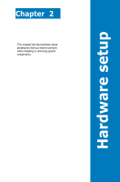
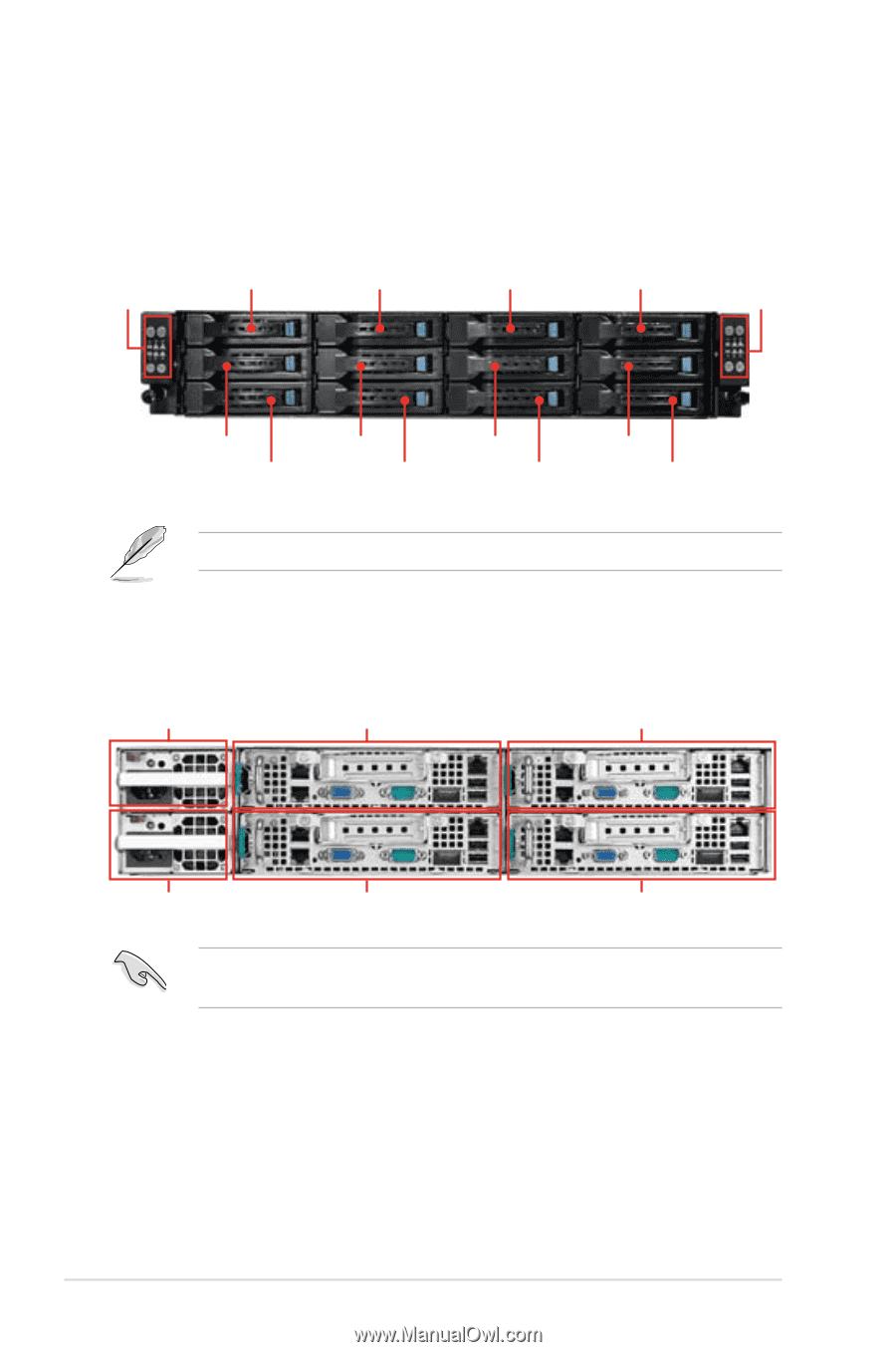
1.4 Front panel features The barebone server displays a simple yet stylish front panel with easily accessible features. The power and reset buttons, LED indicators, optical drive, and two USB ports are located on the front panel. Front panel Node 2 HDD 1 (Node 1) Node 1 HDD 1 (Node 2) HDD 1 (Node 3) Front panel HDD 1 (Node 4) Node 4 Node 3 HDD 2 (Node 1) HDD 2 (Node 2) HDD 2 (Node 3) HDD 2 (Node 4) HDD 3 (Node 1) HDD 3 (Node 2) HDD 3 (Node 3) HDD 3 (Node 4) Refer to section 1.7.1 Front panel LEDs for the LED descriptions. 1.5 Rear panel features PSU 2 Node 4 Node 2 PSU 1 Node 3 Node 1 When installing only two nodes, install the nodes to node slot number 1 and 3 or number 2 and 4. 1-6 Chapter 1: Product introduction
-
 1
1 -
2
-
3
-
4
-
5
-
6
-
7
-
8
-
9
-
10
-
 11
11 -
 12
12 -
 13
13 -
 14
14 -
 15
15 -
 16
16 -
 17
17 -
 18
18 -
 19
19 -
 20
20 -
 21
21 -
22
-
23
-
24
-
25
-
26
-
27
-
28
-
29
-
30
-
31
-
32
-
33
-
34
-
35
-
36
-
37
-
38
-
39
-
40
-
41
-
42
-
43
-
44
-
45
-
46
-
47
-
48
-
49
-
50
-
51
-
52
-
53
-
54
-
55
-
56
-
57
-
58
-
59
-
60
-
61
-
62
-
63
-
64
-
65
-
66
-
67
-
68
-
69
-
70
-
71
-
72
-
73
-
74
-
75
-
76
-
77
-
78
-
79
-
80
-
81
-
82
-
83
-
84
-
85
-
86
-
87
-
88
-
89
-
90
-
91
-
92
-
93
-
94
-
95
-
96
-
97
-
98
-
99
-
100
-
101
-
102
-
103
-
104
-
105
-
106
-
107
-
108
-
109
-
110
-
111
-
112
-
113
-
114
-
115
-
116
-
117
-
118
-
119
-
120
-
121
-
122
-
123
-
124
-
125
-
126
-
127
-
128
-
129
-
130
-
131
-
132
-
133
-
134
-
135
-
136
-
137
-
138
-
139
-
140
-
141
-
142
-
143
-
144
-
145
-
146
-
147
-
148
-
149
-
150
-
151
-
152
-
153
-
154
-
155
-
156
-
157
-
158
-
159
-
160
-
161
-
162
-
163
-
164
-
165
-
166
-
167
-
168
-
169
-
170
-
171
-
172
-
173
-
174
-
175
-
176
-
177
-
178
-
179
-
180
-
181
-
182
-
183
-
184
-
185
-
186
-
187
-
188
-
189
-
190
-
191
-
192
-
193
-
194
-
195
-
196
 |
 |
Chapter 1:
Product introduction
1-6
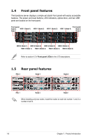
1.4
Front panel features
The barebone server displays a simple yet stylish front panel with easily accessible
features. The power and reset buttons, LED indicators, optical drive, and two USB
ports are located on the front panel.
Refer to section
1.7.1 Front panel LEDs
for the LED descriptions.
Front panel
Node 2
Node 1
Front panel
Node 4
Node 3
HDD 1 (Node 1)
HDD 2 (Node 1)
HDD 3 (Node 1)
HDD 1 (Node 2)
HDD 1 (Node 3)
HDD 1 (Node 4)
HDD 2 (Node 2)
HDD 3 (Node 2)
HDD 2 (Node 3)
HDD 3 (Node 3)
HDD 2 (Node 4)
HDD 3 (Node 4)
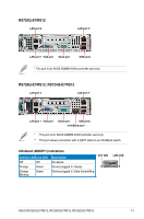
1.5
Rear panel features
PSU 1
Node 3
Node 1
Node 4
Node 2
PSU 2
When installing only two nodes, install the nodes to node slot number 1 and 3 or
number 2 and 4.