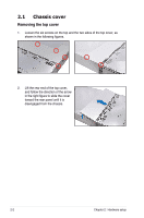
Asus RS726Q-E7 RS12 RS72xQ-E7_RS12 User Manual - Page 27
Push down the right load lever J, plate is fixed by the lever K., Push down the left load lever L
 |
View all Asus RS726Q-E7 RS12 manuals
Add to My Manuals
Save this manual to your list of manuals |
Page 27 highlights
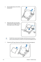
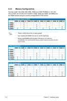
8. Push down the right load lever (J), ensuring that the edge of the load plate is fixed by the lever (K). K J 9. Insert the right load lever under the retention tab. 10. Push down the left load lever (L), and then insert the lever under the retention tab (M). M L ASUS RS720Q-E7/RS12, RS724Q-E7/RS12, RS726Q-E7/RS12 2-7
-
 1
1 -
2
-
3
-
4
-
5
-
6
-
7
-
8
-
9
-
10
-
11
-
12
-
13
-
14
-
15
-
16
-
17
-
18
-
19
-
20
-
21
-
 22
22 -
 23
23 -
 24
24 -
 25
25 -
 26
26 -
 27
27 -
 28
28 -
 29
29 -
 30
30 -
 31
31 -
 32
32 -
33
-
34
-
35
-
36
-
37
-
38
-
39
-
40
-
41
-
42
-
43
-
44
-
45
-
46
-
47
-
48
-
49
-
50
-
51
-
52
-
53
-
54
-
55
-
56
-
57
-
58
-
59
-
60
-
61
-
62
-
63
-
64
-
65
-
66
-
67
-
68
-
69
-
70
-
71
-
72
-
73
-
74
-
75
-
76
-
77
-
78
-
79
-
80
-
81
-
82
-
83
-
84
-
85
-
86
-
87
-
88
-
89
-
90
-
91
-
92
-
93
-
94
-
95
-
96
-
97
-
98
-
99
-
100
-
101
-
102
-
103
-
104
-
105
-
106
-
107
-
108
-
109
-
110
-
111
-
112
-
113
-
114
-
115
-
116
-
117
-
118
-
119
-
120
-
121
-
122
-
123
-
124
-
125
-
126
-
127
-
128
-
129
-
130
-
131
-
132
-
133
-
134
-
135
-
136
-
137
-
138
-
139
-
140
-
141
-
142
-
143
-
144
-
145
-
146
-
147
-
148
-
149
-
150
-
151
-
152
-
153
-
154
-
155
-
156
-
157
-
158
-
159
-
160
-
161
-
162
-
163
-
164
-
165
-
166
-
167
-
168
-
169
-
170
-
171
-
172
-
173
-
174
-
175
-
176
-
177
-
178
-
179
-
180
-
181
-
182
-
183
-
184
-
185
-
186
-
187
-
188
-
189
-
190
-
191
-
192
-
193
-
194
-
195
-
196
 |
 |

2-7
ASUS RS720Q-E7/RS12, RS724Q-E7/RS12, RS726Q-E7/RS12
K
J
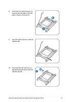
8.
Push down the right load lever (J),
ensuring that the edge of the load
plate is fixed by the lever (K).
9.
Insert the right load lever under the
retention tab.
M
L
10.
Push down the left load lever (L),
and then insert the lever under the
retention tab (M).