Asus RS920-E7 RS8 User Guide - Page 18
Front panel features, Rear panel features
 |
View all Asus RS920-E7 RS8 manuals
Add to My Manuals
Save this manual to your list of manuals |
Page 18 highlights
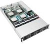
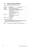
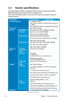
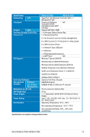
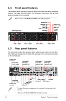
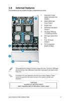
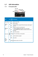
1.4 Front panel features The barebone server displays a simple yet stylish front panel with easily accessible features. The power and reset buttons, LED indicators, optical drive, and two USB ports are located on the front panel. Refer to section 1.7.1 Front panel LEDs for the LED descriptions. ODD dummy cover Reset button Message LED LAN1 LED LAN2 LED HDD Access LED USB ports Location LED Location switch Power LED Power button HDD 1 HDD 5 HDD 2 HDD 6 HDD 3 HDD 7 HDD 4 HDD 8 1.5 Rear panel features The rear panel includes the expansion slots, system power socket, and rear fans. The middle part includes the I/O shield with openings for the rear panel connectors on the motherboard. Power cord connector Redundant power supply 2 Full-length / Full-height Expansion slot 2 Half-length / Low-profile Expansion slot 2 Full-length / Full-height Expansion slot Redundant power supply Power cord connector InfiniBand port USB 3.0 ports VGA port LAN port 4 LAN port 5* USB 2.0 ports LAN port 3 LAN port 2 LAN port 1 • The rear I/O ports do not appear on the rear panel if motherboard is not present. • *The port is for ASUS ASMB6-iKVM controller card only. 1-6 Chapter 1: Product introduction
-
 1
1 -
2
-
3
-
4
-
5
-
6
-
7
-
8
-
9
-
10
-
11
-
12
-
 13
13 -
 14
14 -
 15
15 -
 16
16 -
 17
17 -
 18
18 -
 19
19 -
 20
20 -
 21
21 -
 22
22 -
 23
23 -
24
-
25
-
26
-
27
-
28
-
29
-
30
-
31
-
32
-
33
-
34
-
35
-
36
-
37
-
38
-
39
-
40
-
41
-
42
-
43
-
44
-
45
-
46
-
47
-
48
-
49
-
50
-
51
-
52
-
53
-
54
-
55
-
56
-
57
-
58
-
59
-
60
-
61
-
62
-
63
-
64
-
65
-
66
-
67
-
68
-
69
-
70
-
71
-
72
-
73
-
74
-
75
-
76
-
77
-
78
-
79
-
80
-
81
-
82
-
83
-
84
-
85
-
86
-
87
-
88
-
89
-
90
-
91
-
92
-
93
-
94
-
95
-
96
-
97
-
98
-
99
-
100
-
101
-
102
-
103
-
104
-
105
-
106
-
107
-
108
-
109
-
110
-
111
-
112
-
113
-
114
-
115
-
116
-
117
-
118
-
119
-
120
-
121
-
122
-
123
-
124
-
125
-
126
-
127
-
128
-
129
-
130
-
131
-
132
-
133
-
134
-
135
-
136
-
137
-
138
-
139
-
140
-
141
-
142
-
143
-
144
-
145
-
146
-
147
-
148
-
149
-
150
-
151
-
152
-
153
-
154
-
155
-
156
-
157
-
158
-
159
-
160
-
161
-
162
-
163
-
164
-
165
-
166
-
167
-
168
-
169
-
170
-
171
-
172
-
173
-
174
-
175
-
176
-
177
-
178
-
179
-
180
-
181
-
182
-
183
-
184
-
185
-
186
-
187
-
188
-
189
-
190
-
191
-
192
-
193
-
194
-
195
-
196
-
197
-
198
-
199
-
200
 |
 |