Asus S1-P112 Spresso Hardware User Manual - Page 18
Internal components
 |
View all Asus S1-P112 manuals
Add to My Manuals
Save this manual to your list of manuals |
Page 18 highlights
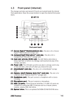
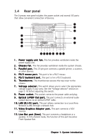
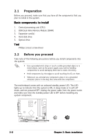
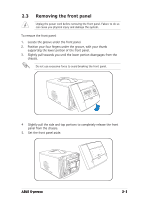
1.5 Internal components The illustration below is the internal view of the system when you remove the top cover. The installed components are labeled for your reference. Proceed to Chapter 2 for instructions on installing other system components. 1 2 3 4 5 6 7 8 1. Optical drive bay 2. HDD drive bay 3. Storage card slot 4. I/O slot 5. DIMM sockets 6. Fan and heatsink assembly 7. AGP card slot 8. PCI card slot 1-8 Chapter 1: System introduction
-
 1
1 -
2
-
3
-
4
-
5
-
6
-
7
-
8
-
9
-
10
-
11
-
12
-
 13
13 -
 14
14 -
 15
15 -
 16
16 -
 17
17 -
 18
18 -
 19
19 -
 20
20 -
 21
21 -
 22
22 -
 23
23 -
24
-
25
-
26
-
27
-
28
-
29
-
30
-
31
-
32
-
33
-
34
-
35
-
36
-
37
-
38
-
39
-
40
-
41
-
42
-
43
-
44
-
45
-
46
-
47
-
48
-
49
-
50
-
51
-
52
-
53
-
54
-
55
-
56
-
57
-
58
-
59
-
60
-
61
-
62
-
63
-
64
-
65
-
66
-
67
-
68
-
69
-
70
-
71
-
72
-
73
-
74
-
75
-
76
-
77
-
78
-
79
-
80
-
81
-
82
-
83
-
84
-
85
-
86
-
87
-
88
-
89
-
90
-
91
-
92
-
93
-
94
-
95
-
96
-
97
-
98
-
99
-
100
-
101
-
102
-
103
-
104
-
105
-
106
 |
 |

1-8
1-8
1-8
1-8
1-8
Chapter 1: System introduction
Chapter 1: System introduction
Chapter 1: System introduction
Chapter 1: System introduction
Chapter 1: System introduction
1.5
Internal components
The illustration below is the internal view of the system when you remove
the top cover. The installed components are labeled for your reference.
Proceed to Chapter 2 for instructions on installing other system
components.
1.
Optical drive bay
2.
HDD drive bay
3.
Storage card slot
4.
I/O slot
5.
DIMM sockets
6.
Fan and heatsink assembly
7.
AGP card slot
8.
PCI card slot
1
2
4
3
5
6
8
7