Asus S1-P112 Spresso Hardware User Manual - Page 53
System power LED 2-pin PLED
 |
View all Asus S1-P112 manuals
Add to My Manuals
Save this manual to your list of manuals |
Page 53 highlights
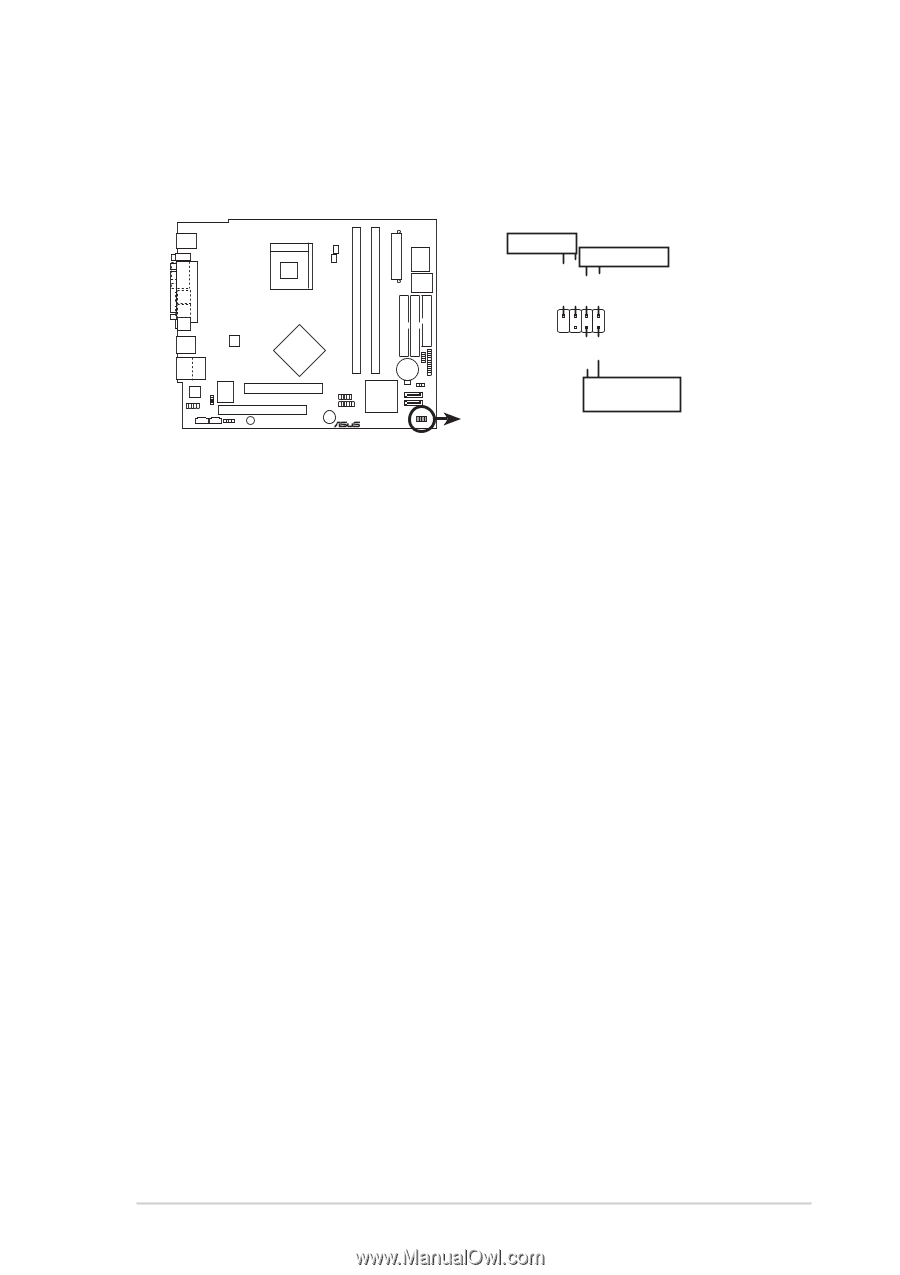
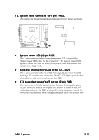
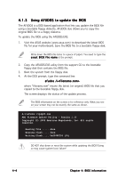
10. System panel connector (8-1 pin PANEL) This connector accommodates several system front panel functions. IDE_LED Power LED IDE_LEDIDE_LED+ PLEDPLED+ PANEL Ground PWR P4P8T ® P4P8T System panel connector ATX Power Switch* * Requires an ATX power supply. • System power LED (2-pin PLED) This 3-pin connector is for the system power LED. Connect the chassis power LED cable to this connector. The system power LED lights up when you turn on the system power, and blinks when the system is in sleep mode. • Hard disk drive activity LED (2-pin IDE_LED) This 2-pin connector is for the HDD Activity LED. Connect the HDD Activity LED cable to this connector. The IDE LED lights up or flashes when data is read from or written to the HDD. • ATX power button/soft-off button (2-pin PWR) This connector is for the system power button. Pressing the power button turns the system on or puts the system in sleep or soft-off mode depending on the BIOS settings. Pressing the power switch for more than four seconds while the system is ON turns the system OFF. ASUS S-presso 3-11
-
 1
1 -
2
-
3
-
4
-
5
-
6
-
7
-
8
-
9
-
10
-
11
-
12
-
13
-
14
-
15
-
16
-
17
-
18
-
19
-
20
-
21
-
22
-
23
-
24
-
25
-
26
-
27
-
28
-
29
-
30
-
31
-
32
-
33
-
34
-
35
-
36
-
37
-
38
-
39
-
40
-
41
-
42
-
43
-
44
-
45
-
46
-
47
-
 48
48 -
 49
49 -
 50
50 -
 51
51 -
 52
52 -
 53
53 -
 54
54 -
 55
55 -
 56
56 -
 57
57 -
 58
58 -
59
-
60
-
61
-
62
-
63
-
64
-
65
-
66
-
67
-
68
-
69
-
70
-
71
-
72
-
73
-
74
-
75
-
76
-
77
-
78
-
79
-
80
-
81
-
82
-
83
-
84
-
85
-
86
-
87
-
88
-
89
-
90
-
91
-
92
-
93
-
94
-
95
-
96
-
97
-
98
-
99
-
100
-
101
-
102
-
103
-
104
-
105
-
106
 |
 |