Asus S1-P112 Spresso Hardware User Manual - Page 35
secondary IDE connector
 |
View all Asus S1-P112 manuals
Add to My Manuals
Save this manual to your list of manuals |
Page 35 highlights
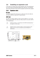
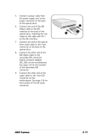
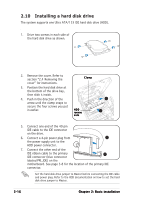
5. Connect a power cable from the power supply unit to the power connector at the back of the optical drive. 6. Connect one end of the IDE ribbon cable to the IDE interface at the back of the optical drive, matching the red stripe on the cable with Pin 1 on the IDE interface. 7. Connect one end of the optical drive audio cable to the 4-pin connector at the back of the optical drive. 8. Connect the other end of the IDE ribbon cable to the secondary IDE connector (black connector labeled SEC_IDE) on the motherboard. See page 3-8 for the location of the secondary IDE connector. 9. Connect the other end of the audio cable to the 4-pin CD1 connector on the motherboard. See page 3-8 for the location of the CD audio connector. 5 6 7 ASUS S-presso 2-15
-
 1
1 -
2
-
3
-
4
-
5
-
6
-
7
-
8
-
9
-
10
-
11
-
12
-
13
-
14
-
15
-
16
-
17
-
18
-
19
-
20
-
21
-
22
-
23
-
24
-
25
-
26
-
27
-
28
-
29
-
 30
30 -
 31
31 -
 32
32 -
 33
33 -
 34
34 -
 35
35 -
 36
36 -
 37
37 -
 38
38 -
 39
39 -
 40
40 -
41
-
42
-
43
-
44
-
45
-
46
-
47
-
48
-
49
-
50
-
51
-
52
-
53
-
54
-
55
-
56
-
57
-
58
-
59
-
60
-
61
-
62
-
63
-
64
-
65
-
66
-
67
-
68
-
69
-
70
-
71
-
72
-
73
-
74
-
75
-
76
-
77
-
78
-
79
-
80
-
81
-
82
-
83
-
84
-
85
-
86
-
87
-
88
-
89
-
90
-
91
-
92
-
93
-
94
-
95
-
96
-
97
-
98
-
99
-
100
-
101
-
102
-
103
-
104
-
105
-
106
 |
 |