Asus TUF H370-PRO GAMING Users Manual English - Page 12
Layout contents, Connectors/Jumpers/Slots
 |
View all Asus TUF H370-PRO GAMING manuals
Add to My Manuals
Save this manual to your list of manuals |
Page 12 highlights
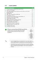
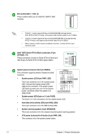
1.2.1 Layout contents Connectors/Jumpers/Slots 1. ATX power connectors (24-pin EATXPWR, 8-pin EATX12V) 2. Intel® LGA1151 CPU socket 3. CPU, chassis, and AIO pump fan connectors (4-pin CPU_FAN, 4-pin CHA_FAN1~2, 4-pin AIO_PUMP FAN) 4. DDR4 DIMM slots 5. USB 3.1 Gen 1 connector (20-1 pin U31G1_56) 6. M.2 sockets (M.2_1; M.2_2) 7. Intel® H370 Serial ATA 6.0 Gb/s connector (7-pin SATA6G_1~6) 8. System panel connector (20-3 pin PANEL) 9. Clear RTC RAM (2-pin CLRTC) 10. USB 2.0 connectors (10-1 pin USB1213, USB1114) 11. AURA RGB header (4-pin RGB_HEADER) 12. Serial port connector (10-1 pin COM) 13. Front panel audio connector (10-1 pin AAFP) 14. Digital audio connector (4-1 pin SPDIF_OUT) 15. PCI Express 3.0/2.0 x1 slots 16. PCI Express 3.0/2.0 x16 slots Page 1-2 1-3 1-3 1-3 1-3 1-4 1-4 1-4 1-5 1-5 1-5 1-5 1-6 1-6 1-6 1-6 ATX power connectors (24-pin EATXPWR, 8-pin EATX12V) Correctly orient the ATX power supply plugs into these connectors and push down firmly until the connectors completely fit. EATX12V GND GND GND GND PIN 1 +12V DC +12V DC +12V DC +12V DC EATXPWR +3 Volts +12 Volts +12 Volts +5V Standby Power OK GND +5 Volts GND +5 Volts GND +3 Volts +3 Volts PIN 1 GND +5 Volts +5 Volts +5 Volts -5 Volts GND GND GND PSON# GND -12 Volts +3 Volts • For a fully configured system, we recommend that you use a power supply unit (PSU) that complies with ATX 12 V Specification 2.0 (or later version) and provides a minimum power of 350 W. This PSU type has 24-pin and 8-pin power plugs. • We recommend that you use a PSU with higher power output when configuring a system with more power-consuming devices or when you intend to install additional devices. The system may become unstable or may not boot up if the power is inadequate. 1-2 Chapter 1: Product Introduction
-
 1
1 -
2
-
3
-
4
-
5
-
6
-
 7
7 -
 8
8 -
 9
9 -
 10
10 -
 11
11 -
 12
12 -
 13
13 -
 14
14 -
 15
15 -
 16
16 -
 17
17 -
18
-
19
-
20
-
21
-
22
-
23
-
24
-
25
-
26
-
27
-
28
-
29
-
30
-
31
-
32
-
33
-
34
-
35
-
36
-
37
-
38
-
39
-
40
 |
 |
