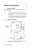
Asus TUF H370-PRO GAMING Users Manual English - Page 16
VGA configuration, PCI Express operating mode, PCIe 3.0 x16_1 gray, PCIe 3.0 x16_2
 |
View all Asus TUF H370-PRO GAMING manuals
Add to My Manuals
Save this manual to your list of manuals |
Page 16 highlights
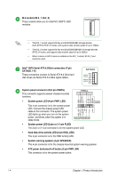
Front panel audio connector (10-1 pin AAFP) This connector is for a chassis-mounted front panel audio I/O module that supports HD Audio standard. Connect one end of the front panel audio I/O module cable to this connector. Digital audio connector (4-1 pin SPDIF_OUT) This connector is for an additional Sony/Philips Digital Interface (S/PDIF) port. Connect the S/PDIF Out module cable to this connector, then install the module to a slot opening at the back of the system chassis. +5V SPDIFOUT GND PORT1 L PORT1 R PORT2 R SENSE_SEND PORT2 L AGND NC SENSE1_RETUR SENSE2_RETUR AAFP HD-audio-compliant pin definition SPDIF_OUT We recommend that you connect a high-definition front panel audio module to this connector to avail of the motherboard's high-definition audio capability. PCI Express 3.0/2.0 x1 slots This motherboard has four PCI Express 3.0/2.0 x1 slots that support PCI Express x1 network cards, SCSI cards, and other cards that comply with the PCI Express specifications. PCI Express 3.0/2.0 x16 slots This motherboard supports two PCI Express 3.0/2.0 x16 graphic cards that comply with the PCI Express specifications. Actual PCI Express speeds varies per BIOS settings. VGA configuration Single VGA/PCIe card Dual VGA/PCIe cards PCI Express operating mode PCIe 3.0 x16_1 (gray) PCIe 3.0 x16_2 x16 (Recommended for N/A single VGA card) x16 x4 • In single VGA card mode, use the PCIe 3.0 x16_1 slot (gray) for a PCI Express x16 graphics card to get better performance. • We recommend that you provide sufficient power when running CrossFireX™ mode. • Connect a chassis fan to the motherboard connector labeled CHA_FAN1/2 when using multiple graphics cards for better thermal environment. 1-6 Chapter 1: Product Introduction
-
 1
1 -
2
-
3
-
4
-
5
-
6
-
7
-
8
-
9
-
10
-
 11
11 -
 12
12 -
 13
13 -
 14
14 -
 15
15 -
 16
16 -
 17
17 -
 18
18 -
 19
19 -
 20
20 -
 21
21 -
22
-
23
-
24
-
25
-
26
-
27
-
28
-
29
-
30
-
31
-
32
-
33
-
34
-
35
-
36
-
37
-
38
-
39
-
40
 |
 |
