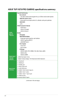
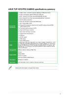
Asus TUF H370-PRO GAMING Users Manual English - Page 13
USB 3.1 Gen 1 connector 20-1 pin U31G1_56, CPU_FAN, 4-pin CHA_FAN1~2
 |
View all Asus TUF H370-PRO GAMING manuals
Add to My Manuals
Save this manual to your list of manuals |
Page 13 highlights
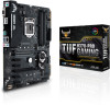
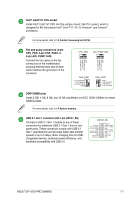
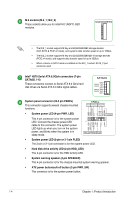
Intel® LGA1151 CPU socket Install Intel® LGA1151 CPU into this surface mount LGA1151 socket, which is designed for 8th Generation Intel® Core™ i7 / i5 / i3, Pentium®, and Celeron® processors. For more details, refer to 1.3 Central Processing Unit (CPU). Fan and pump connectors (4-pin CPU_FAN, 4-pin CHA_FAN1~2, 4-pin AIO_PUMP FAN) Connect the fan cables to the fan connectors on the motherboard, ensuring that the black wire of each cable matches the ground pin of the connector. CPU_FAN AIO_PUMP FAN CPU FAN PWM CPU FAN IN CPU FAN PWR GND AIO_PUMP PWM AIO_PUMP IN AIO_PUMP PWR GND CHA_FAN1 CHA FAN PWM CHA FAN IN CHA FAN PWR GND CHA_FAN2 GND CHA FAN PWR CHA FAN IN CHA FAN PWM DDR4 DIMM slots Install 2 GB, 4 GB, 8 GB, and 16 GB unbuffered non-ECC DDR4 DIMMs into these DIMM sockets. For more details, refer to 1.4 System memory. USB 3.1 Gen 1 connector (20-1 pin U31G1_56) Connect a USB 3.1 Gen 1 module to any of these connectors for additional USB 3.1 Gen 1 front or rear panel ports. These connectors comply with USB 3.1 Gen 1 specifications and provides faster data transfer speeds of up to 5 Gbps, faster charging time for USBchargeable devices, optimized power efficiency, and backward compatibility with USB 2.0 U31G1_56 USB3+5V IntA_P2_SSRXIntA_P2_SSRX+ GND IntA_P2_SSTXIntA_P2_SSTX+ GND IntA_P2_DIntA_P2_D+ PIN 1 USB3+5V IntA_P1_SSRXIntA_P1_SSRX+ GND IntA_P1_SSTXIntA_P1_SSTX+ GND IntA_P1_DIntA_P1_D+ GND ASUS TUF H370-PRO GAMING 1-3
-
 1
1 -
2
-
3
-
4
-
5
-
6
-
7
-
 8
8 -
 9
9 -
 10
10 -
 11
11 -
 12
12 -
 13
13 -
 14
14 -
 15
15 -
 16
16 -
 17
17 -
 18
18 -
19
-
20
-
21
-
22
-
23
-
24
-
25
-
26
-
27
-
28
-
29
-
30
-
31
-
32
-
33
-
34
-
35
-
36
-
37
-
38
-
39
-
40
 |
 |
