Asus TUF H370-PRO GAMING Users Manual English - Page 14
M.2 sockets M.2_1; M.2_2, Intel, H370 Serial ATA 6.0Gb/s connectors 7-pin, SATA6G_1-6
 |
View all Asus TUF H370-PRO GAMING manuals
Add to My Manuals
Save this manual to your list of manuals |
Page 14 highlights
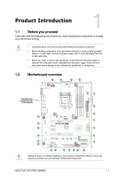
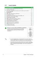
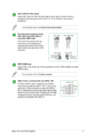
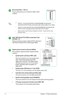
M.2 sockets (M.2_1; M.2_2) These sockets allow you to install M.2 (NGFF) SSD modules. M.2(SOCKET3) • The M.2_1 socket supports M Key and 2242/2260/2280 storage devices (both SATA & PCIE x2 mode), and supports data transfer speed of up to 16Gb/s. • The M.2_2 socket supports M Key and 2242/2260/2280/22110 storage devices (PCIE x4 mode), and supports data transfer speed of up to 32Gb/s. • When a device in SATA mode is installed on the M.2_1 socket, SATA_2 port cannot be used. Intel® H370 Serial ATA 6.0Gb/s connectors (7-pin SATA6G_1-6) These connectors connect to Serial ATA 6.0 Gb/s hard disk drives via Serial ATA 6.0 Gb/s signal cables. SATA6G GND RSATA_TXP RSATA_TXN GND RSATA_RXN RSATA_RXP GND System panel connector (20-3 pin PANEL) This connector supports several chassis-mounted functions. • System power LED (4-pin PWR_LED) This 4-pin connector is for the system power LED. Connect the chassis power LED cable to this connector. The system power LED lights up when you turn on the system power, and blinks when the system is in sleep mode. • System power LED (2-pin or 3-1 pin PLED) The 2-pin or 3-1 pin connector is for the system power LED. • Hard disk drive activity LED (2-pin HDD_LED) This 2-pin connector is for the HDD Activity LED. • System warning speaker (4-pin SPEAKER) This 4-pin connector is for the chassis-mounted system warning speaker. • ATX power button/soft-off button (2-pin PWR_SW) This connector is for the system power button. 1-4 Chapter 1: Product Introduction
-
 1
1 -
2
-
3
-
4
-
5
-
6
-
7
-
8
-
 9
9 -
 10
10 -
 11
11 -
 12
12 -
 13
13 -
 14
14 -
 15
15 -
 16
16 -
 17
17 -
 18
18 -
 19
19 -
20
-
21
-
22
-
23
-
24
-
25
-
26
-
27
-
28
-
29
-
30
-
31
-
32
-
33
-
34
-
35
-
36
-
37
-
38
-
39
-
40
 |
 |
