Asus TX97-X User Manual - Page 13
ASUS TX97-X User's Manual, Jumpers, Expansion Slots, Connectors - ram
 |
View all Asus TX97-X manuals
Add to My Manuals
Save this manual to your list of manuals |
Page 13 highlights
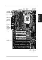
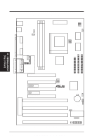
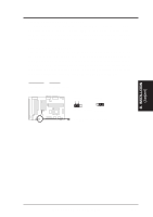
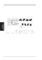
III. INSTALLATION (Map of Board) III. INSTALLATION Jumpers 1) SIO 2) BBLKW 3) AUDIO 4) VOLCTL 5) RTCLR 6) FS0, FS1, FS2 7) BF0, BF1 8) VID0, VID1, VID2 p. 15 Multi-I/O Selection (Enable/Disable) p. 15 Flash ROM Boot Block Program (Disable/Enable) p. 16 Onboard Audio (Disable/Enable) p. 16 Digital Volume Level Control (Up/Down) p. 17 Real Time Clock RAM (Operation/Clear Data) p. 18 CPU External Clock (BUS) Frequency Selection p. 18 CPU:BUS Frequency Ratio p. 19 CPU Voltage Regulator Output Selection Expansion Slots 1) DIMM Sockets 2) CPU ZIF Socket 7 3) ISA Slots 4) PCI Slots p. 21 168-Pin DIMM Memory Expansion Sockets p. 23 Central Processing Unit (CPU) Socket p. 24 16-bit ISA Bus Expansion Slots p. 24 32-bit PCI Bus Expansion Slots Connectors 1) PS2KEYBOARD 2) PS2MOUSE 3) PRINTER 4) COM1, COM2 5) AUDIO (optional) 6) GAME (optional) 7) USB 8) FLOPPY 9) FANPWR1, 2, 3 10) CHASSIS 11) Primary / Second IDE 12) IDELED 13) MSG LED (PANEL) 14) SMI (PANEL) 15) PWR SW (CON1) 16) RESET (PANEL) 17) KEYLOCK (PANEL) 18) SPEAKER (PANEL) 19) IR 20) ATXPWR p. 26 PS/2 Keyboard Connector (6-pin Female) p. 26 PS/2 Mouse Connector (6-pin Female) p. 27 Parallel (Printer) Port Connector (25-pin Female) p. 27 Serial Port COM1 & COM2 (Two 9-pin Female) p. 27 Audio Port -Line Out, Line In, Mic (Three 1/8" Female) p. 28 Joystick/Midi Connector (15-pin Female) p. 28 Universal Serial BUS Ports 1 & 2 (Two 4-pin Female) p. 28 Floppy Drive Connector (34-pin Block) p. 29 1Chassis,2CPU,3PowerSupplyFanPowerLead(3-pinBlock) p. 29 Chassis Open Alarm Lead (3-pin Block) p. 30 Primary / Secondary IDE Connector (40-pin Blocks) p. 30 IDE LED Activity Light p. 31 System Message LED (2-pins) p. 31 SMI Switch Lead (2-pins) p. 31 ATX Power & Soft-Off Switch Lead (2-pins) p. 31 Reset Switch Lead (2-pins) p. 31 Keyboard Lock Switch Lead (5-pins) p. 31 Speaker Output Connector (4-pins) p. 32 Infrared Port Module Connector p. 32 Motherboard Power Connector (20-pin Block) ASUS TX97-X User's Manual 13
-
 1
1 -
2
-
3
-
4
-
5
-
6
-
7
-
 8
8 -
 9
9 -
 10
10 -
 11
11 -
 12
12 -
 13
13 -
 14
14 -
 15
15 -
 16
16 -
 17
17 -
 18
18 -
19
-
20
-
21
-
22
-
23
-
24
-
25
-
26
-
27
-
28
-
29
-
30
-
31
-
32
-
33
-
34
-
35
-
36
-
37
-
38
-
39
-
40
-
41
-
42
-
43
-
44
-
45
-
46
-
47
-
48
-
49
-
50
-
51
-
52
-
53
-
54
-
55
-
56
-
57
-
58
-
59
-
60
-
61
-
62
-
63
-
64
 |
 |
