Asus V2-P5G965 User Manual - Page 34
Installing an optical drive
 |
View all Asus V2-P5G965 manuals
Add to My Manuals
Save this manual to your list of manuals |
Page 34 highlights
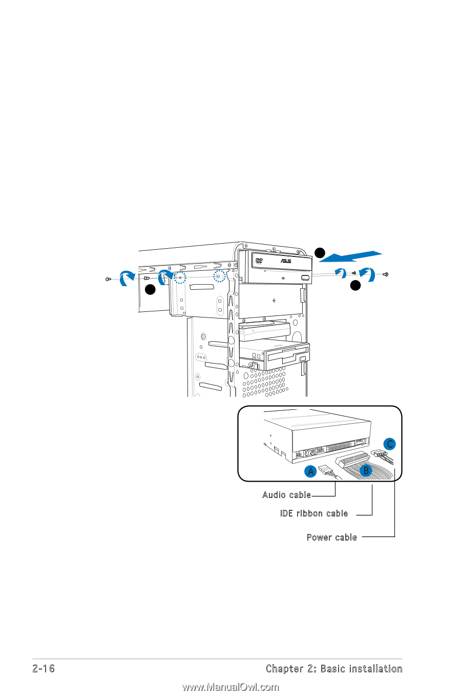
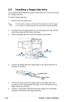
2.7 Installing an optical drive Refer to the instructions in this section if you wish to install a new optical drive. Follow these steps to install an optical drive: 1. Place the chassis upright. 2. Remove the drive slot metal plate cover. 3. Insert the optical drive into the upper 5.25-inch drive bay and carefully push the optical drive into the bay until its screw holes align with the holes on the bay as shown. 4. Secure the optical drive with two screws on both sides of the bay. 3 4 4 5. Connect the audio (A), IDE (B), and power (C) plugs to connectors at the back of the drive. 6. Connect the other end of the IDE ribbon cable to the secondary IDE connector (labeled SEC_IDE) on the motherboard. See page 4-6 for the location of this connector. C A B Audio cable IDE ribbon cable Power cable 7. Remove the dummy drive slot cover from the front panel. 8. Replace the front panel. Refer to section "2.11 Removing the bay covers and reinstalling the front panel assembly and side cover" on page 2-22 for details. 2-16 Chapter 2: Basic installation
-
 1
1 -
2
-
3
-
4
-
5
-
6
-
7
-
8
-
9
-
10
-
11
-
12
-
13
-
14
-
15
-
16
-
17
-
18
-
19
-
20
-
21
-
22
-
23
-
24
-
25
-
26
-
27
-
28
-
 29
29 -
 30
30 -
 31
31 -
 32
32 -
 33
33 -
 34
34 -
 35
35 -
 36
36 -
 37
37 -
 38
38 -
 39
39 -
40
-
41
-
42
-
43
-
44
-
45
-
46
-
47
-
48
-
49
-
50
-
51
-
52
-
53
-
54
-
55
-
56
-
57
-
58
-
59
-
60
-
61
-
62
-
63
-
64
-
65
-
66
-
67
-
68
-
69
-
70
-
71
-
72
-
73
-
74
-
75
-
76
-
77
-
78
-
79
-
80
-
81
-
82
-
83
-
84
-
85
-
86
-
87
-
88
-
89
-
90
-
91
-
92
-
93
-
94
-
95
-
96
-
97
-
98
-
99
-
100
 |
 |