Asus V2-P5G965 User Manual - Page 38
Installing a floppy disk drive
 |
View all Asus V2-P5G965 manuals
Add to My Manuals
Save this manual to your list of manuals |
Page 38 highlights
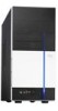
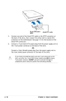
2.9 Installing a floppy disk drive The V-Series P5G965 Barebone system comes with one 3.25-inch drive bay for a floppy disk drive. To install a floppy disk drive: 1. Remove the front panel cover. For instructions on how to remove the front panel cover, refer to page 2-3 of section "2.3 Removing the side cover and front panel assembly". 2. Carefully insert the floppy disk drive into the floppy drive bay until the screw holes align with the holes on the bay. 3. Secure the floppy disk drive with two screws on both sides. 3 3 2 4. Connect the floppy disk drive signal cable to the signal connector at the back of the drive. Power cable Floppy ribbon cable 5. Connect the other end of the signal cable to the floppy disk drive connector on the motherboard. See page 4-6 for the location of the floppy disk drive connector. 6. Connect a 4-pin power cable from the power supply unit to the power connector at the back of the floppy disk drive. 2-20 Chapter 2: Basic installation
-
 1
1 -
2
-
3
-
4
-
5
-
6
-
7
-
8
-
9
-
10
-
11
-
12
-
13
-
14
-
15
-
16
-
17
-
18
-
19
-
20
-
21
-
22
-
23
-
24
-
25
-
26
-
27
-
28
-
29
-
30
-
31
-
32
-
 33
33 -
 34
34 -
 35
35 -
 36
36 -
 37
37 -
 38
38 -
 39
39 -
 40
40 -
 41
41 -
 42
42 -
 43
43 -
44
-
45
-
46
-
47
-
48
-
49
-
50
-
51
-
52
-
53
-
54
-
55
-
56
-
57
-
58
-
59
-
60
-
61
-
62
-
63
-
64
-
65
-
66
-
67
-
68
-
69
-
70
-
71
-
72
-
73
-
74
-
75
-
76
-
77
-
78
-
79
-
80
-
81
-
82
-
83
-
84
-
85
-
86
-
87
-
88
-
89
-
90
-
91
-
92
-
93
-
94
-
95
-
96
-
97
-
98
-
99
-
100
 |
 |