Asus VivoMini UN42 VivoMini memory wireless card and solid state driveSSD inst - Page 4
illustration below
 |
View all Asus VivoMini UN42 manuals
Add to My Manuals
Save this manual to your list of manuals |
Page 4 highlights
9. Reattach the screws to secure the cover back on the bottom side of the main box. 10. Place the rubber foot on each screw hole. Refer to the illustration for more details. IMPORTANT! A number is printed under each rubber foot and this number corresponds to that rubber foot's location on the cover. Follow the orientation of each rubber foot and the number sequence shown in the illustration below. The rubber foot fits in only one orientation. Note the position of the hole on each rubber foot, as shown in the illustration below NOTE: If you want to remove the rubber foot, use a flathead screwdriver or a straightened paper clip to do so. 4
-
 1
1 -
 2
2 -
 3
3 -
 4
4 -
 5
5 -
 6
6 -
 7
7 -
 8
8 -
 9
9 -
 10
10 -
11
-
12
-
13
-
14
-
15
-
16
 |
 |

4
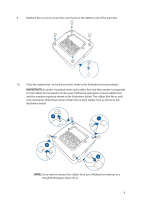
10.
Place the rubber foot
on each screw hole. Refer to the illustration for more details.
IMPORTANT!
A number is printed under each rubber foot and this number corresponds
to that rubber foot’s location on the cover. Follow the orientation of each rubber foot
and the number sequence shown in the illustration below. The rubber foot fits in only
one orientation. Note the position of the hole on each rubber foot, as shown in the
illustration below
NOTE:
If you want to remove the rubber foot, use a flathead screwdriver or a
straightened paper clip to do so.
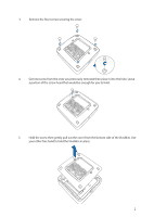
9.
Reattach the screws to secure the cover back on the bottom side of the main box.