Asus Z97-P User Guide - Page 14
Central Processing Unit (CPU), Layout contents
 |
View all Asus Z97-P manuals
Add to My Manuals
Save this manual to your list of manuals |
Page 14 highlights
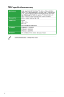
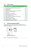
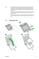
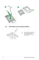
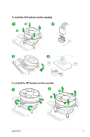
1.2.4 Layout contents Connectors/Jumpers/Slots/LED 1. CPU and chassis fan connectors (4-pin CPU_FAN, 4-pin CHA_FAN1/2) 2. ATX power connectors (24-pin EATXPWR, 8-pin EATX12V) 3. LGA1150 CPU socket 4. DDR3 DIMM slots 5. Intel® Z97 Serial ATA 6.0 Gb/s connectors (7-pin SATA6G_1-4) 6. USB 3.0 connector (20-1 pin USB3_12) 7. M.2 Socket 3 8. Speaker connector (4-pin SPEAKER) 9. System panel connector (10-1 pin F_PANEL) 10. Clear RTC RAM (3-pin CLRTC) 11. USB 2.0 connectors (10-1 pin USB910, USB1112, USB1314) 12. TPM connector (20-1 pin TPM) 13. Serial port connector (10-1 pin COM) 14. Digital audio connector (4-1 pin SPDIF_OUT) 15. Front panel audio connector (10-1 pin AAFP) Page 1-15 1-18 1-4 1-8 1-16 1-21 1-21 1-18 1-20 1-12 1-19 1-19 1-15 1-17 1-17 1.3 Central Processing Unit (CPU) This motherboard comes with a surface mount LGA1150 socket designed for the 4th Generation, New 4th Generation and 5th Generation Intel® Core™ i7 / Core™ i5 / Core™ i3, Pentium® , Celeron® processors. Z97-P Z97-P CPU socket LGA1150 Unplug all power cables before installing the CPU. 1-4 Chapter 1: Product introduction
-
 1
1 -
2
-
3
-
4
-
5
-
6
-
7
-
8
-
 9
9 -
 10
10 -
 11
11 -
 12
12 -
 13
13 -
 14
14 -
 15
15 -
 16
16 -
 17
17 -
 18
18 -
 19
19 -
20
-
21
-
22
-
23
-
24
-
25
-
26
-
27
-
28
-
29
-
30
-
31
-
32
-
33
-
34
-
35
-
36
-
37
-
38
-
39
-
40
-
41
-
42
-
43
-
44
-
45
-
46
-
47
-
48
-
49
-
50
-
51
-
52
-
53
-
54
-
55
-
56
-
57
-
58
-
59
-
60
-
61
-
62
-
63
-
64
-
65
-
66
-
67
-
68
-
69
-
70
-
71
-
72
-
73
-
74
-
75
-
76
-
77
-
78
-
79
-
80
-
81
-
82
-
83
-
84
-
85
-
86
 |
 |
