Asus Z97-P User Guide - Page 29
Z97-P, TPM connector, TPM connector 20-1 pin TPM, USB 2.0 connectors 10-1 pin USB910; USB1112; USB1314
 |
View all Asus Z97-P manuals
Add to My Manuals
Save this manual to your list of manuals |
Page 29 highlights
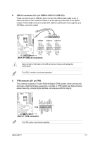
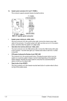
8. USB 2.0 connectors (10-1 pin USB910; USB1112; USB1314) These connectors are for USB 2.0 ports. Connect the USB module cable to any of these connectors, then install the module to a slot opening at the back of the system chassis. These USB connectors comply with USB 2.0 specification that supports up to 480 Mbps connection speed. USB910 USB1112 USB1314 USB+5V USB_P9USB_P9+ GND NC USB+5V USB_P11USB_P11+ GND NC USB+5V USB_P13USB_P13+ GND NC Z97-P PIN 1 PIN 1 PIN 1 USB+5V USB_P10USB_P10+ GND USB+5V USB_P12USB_P12+ GND USB+5V USB_P14USB_P14+ GND Z97-P USB2.0 connectors Never connect a 1394 cable to the USB connectors. Doing so will damage the motherboard! The USB 2.0 module is purchased separately. 9. TPM connector (20-1 pin TPM) This connector supports a Trusted Platform Module (TPM) system, which can securely store keys, digital certificates, passwords, and data. A TPM system also helps enhance network security, protects digital identities, and ensures platform integrity. LPCPD# GND +3VSB NC LAD0 +3V LAD3 LREST# LFRAME# LCLK PIN 1 Z97-P TPM NC CLKRUN# SERIRQ NC GND LAD1 LAD2 NC GND Z97-P TPM connector The TPM module is purchased separately. ASUS Z97-P 1-19
-
 1
1 -
2
-
3
-
4
-
5
-
6
-
7
-
8
-
9
-
10
-
11
-
12
-
13
-
14
-
15
-
16
-
17
-
18
-
19
-
20
-
21
-
22
-
23
-
 24
24 -
 25
25 -
 26
26 -
 27
27 -
 28
28 -
 29
29 -
 30
30 -
 31
31 -
 32
32 -
 33
33 -
 34
34 -
35
-
36
-
37
-
38
-
39
-
40
-
41
-
42
-
43
-
44
-
45
-
46
-
47
-
48
-
49
-
50
-
51
-
52
-
53
-
54
-
55
-
56
-
57
-
58
-
59
-
60
-
61
-
62
-
63
-
64
-
65
-
66
-
67
-
68
-
69
-
70
-
71
-
72
-
73
-
74
-
75
-
76
-
77
-
78
-
79
-
80
-
81
-
82
-
83
-
84
-
85
-
86
 |
 |
