Asus p4r800vm P4R800-VM User Manual - Page 32
Serial port connector 10-1 pin COM1, Front panel audio connector 10-1 pin FP_AUDIO1
 |
View all Asus p4r800vm manuals
Add to My Manuals
Save this manual to your list of manuals |
Page 32 highlights
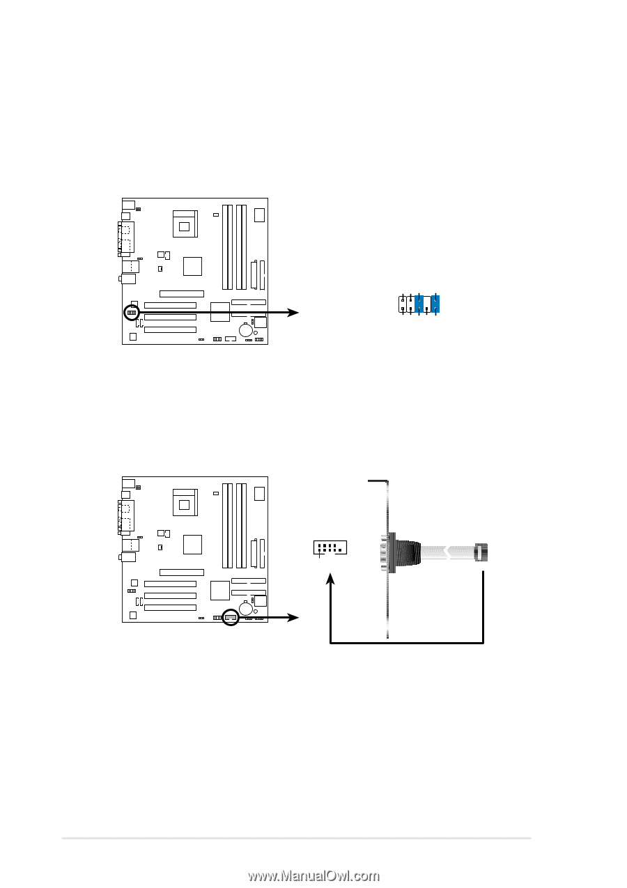
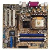
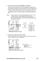
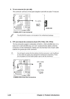
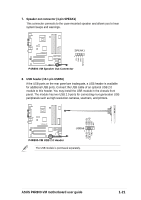
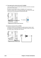
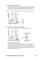
9. Front panel audio connector (10-1 pin FP_AUDIO1) This is an interface for the front panel cable that allows convenient connection and control of audio devices. Be default, the pins labeled LINE OUT_R/BLINE_OUT_R and the pins LINE OUT_L/BLINE_OUT_L are shorted with jumper caps. Remove the caps only when you are connecting the front panel audio cable. AGND +5VA BLINE_OUT_R BLINE_OUT_L P4R800-VM FP_AUDIO1 MIC2 MICPWR Line out_R NC Line out_L P4R800-VM Front Panel Audio Connector 10. Serial port connector (10-1 pin COM1) This green connector accommodates the bundled serial port module. Install the module into a slot opening at the back of the system chassis, the connect the module's green cable plug to this connector. P4R800-VM COM1 PIN 1 P4R800-VM Serial COM1 Bracket 1-22 Chapter 1: Product introduction
-
 1
1 -
2
-
3
-
4
-
5
-
6
-
7
-
8
-
9
-
10
-
11
-
12
-
13
-
14
-
15
-
16
-
17
-
18
-
19
-
20
-
21
-
22
-
23
-
24
-
25
-
26
-
 27
27 -
 28
28 -
 29
29 -
 30
30 -
 31
31 -
 32
32 -
 33
33 -
 34
34 -
 35
35 -
 36
36 -
 37
37 -
38
-
39
-
40
-
41
-
42
-
43
-
44
-
45
-
46
-
47
-
48
-
49
-
50
-
51
-
52
-
53
-
54
-
55
-
56
-
57
-
58
-
59
-
60
-
61
-
62
-
63
-
64
 |
 |