Audiovox VOH1042DL Owners Manual - Page 13
Typical System Connections - harness
 |
UPC - 044476007095
View all Audiovox VOH1042DL manuals
Add to My Manuals
Save this manual to your list of manuals |
Page 13 highlights
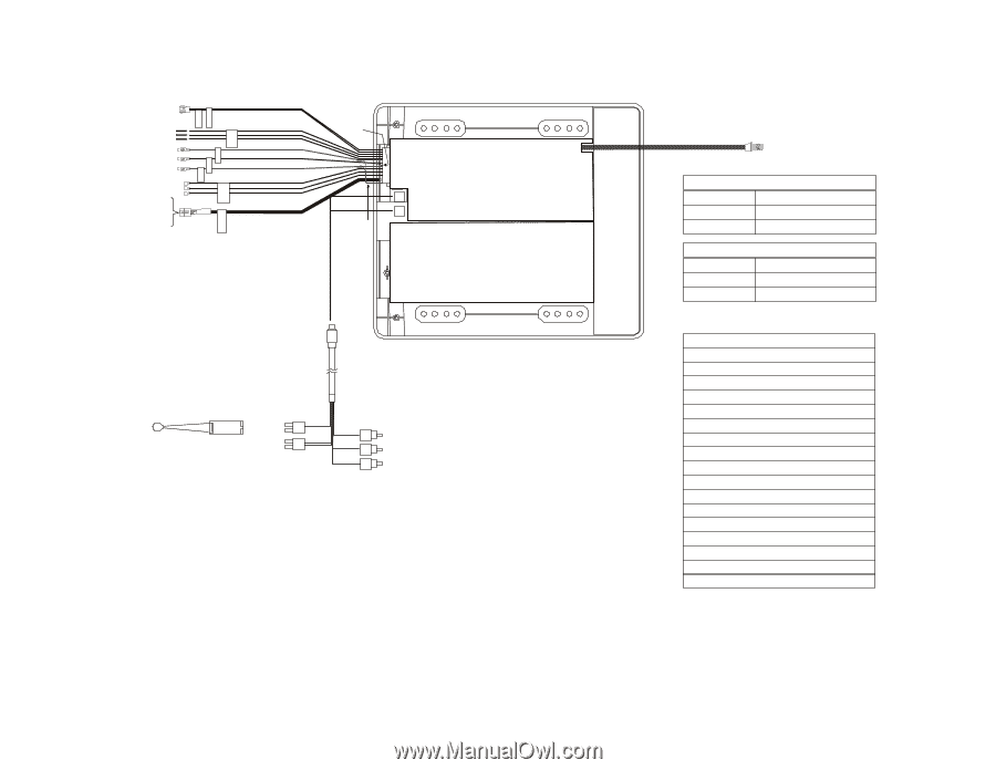
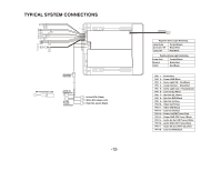
TYPICAL SYSTEM CONNECTIONS 1 2 3 4 5 6 10 12 7 8 14 9 13 17 16 15 GND) (R EW +2V)1 WER( O P O P L UTO -VOUT LINE R -OUT LI NE N E LI M E DO O W T GHT'S LI CTIONNNE CO R O PEAKRE S N E HHOEADP N IONECT ON C R TTEIM RANTS TO M F 11 D IN 1 D IN 2 18 Accessor Harness IR Transmitter LED 2 PIN IR Connector 4 PIN Power Connector Yellow RCA (Video) White RCA (Audio Left) Red RCA (Audio Right) -12- Antenna Negative Dome Light Switching Lamp Auto Constant 12V Lamp ON Purple/Brown Black/Red Red/Black Positive Dome Light Switching Lamp Auto Ground 12Vdc Purple/Brown Black/Red Red/Black PIN 1 - Power/Red PIN 2 - Power GND/Black PIN 3 - Dome Light ON - Red/Black PIN 4 - Lamp Common - Black/Red PIN 5 - Dome Light Auto - Purple/Brown PIN 6 - Line Out (L)/White PIN 7 - Spk Out (R) /Green PIN 8 - Spk Out-GND/Black PIN 9 - Spk Out (L)/Grey PIN 10 - Video Out/Yellow PIN 11 - Video GND/Black PIN 12 - Line Out (R)/Red PIN 13 - Power 12V(FM Trans.)/Red PIN 14 - Power GND (FM Trans.)/Black PIN 15 - Audio (L) Out (FM Trans.)/White PIN 16 - Audio GND (FM Trans.)/Black PIN 17 - Audio (R) Out (FM Trans.)/Red PIN 18 - Line Out GND/Black
-
 1
1 -
2
-
3
-
4
-
5
-
6
-
7
-
 8
8 -
 9
9 -
 10
10 -
 11
11 -
 12
12 -
 13
13 -
 14
14 -
 15
15 -
 16
16
 |
 |