Autodesk 05720-017408-9621 Tutorial
Autodesk 05720-017408-9621 - AE AUTOCAD LT 2000I LAB-PK 10U CD Manual
 |
UPC - 606121033783
View all Autodesk 05720-017408-9621 manuals
Add to My Manuals
Save this manual to your list of manuals |
Autodesk 05720-017408-9621 manual content summary:
- Autodesk 05720-017408-9621 | Tutorial - Page 1
Randy H. Shih Jack Zecher PUBLICATIONS WWW.SDCACAD.COM - Autodesk 05720-017408-9621 | Tutorial - Page 2
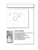
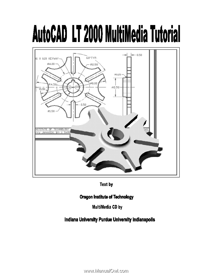
AutoCAD® LT 2000 MultiMedia Tutorial 1-1 Lesson 1 Geometric Construction Basics - Autodesk 05720-017408-9621 | Tutorial - Page 3
entities. In this lesson, we will examine the different ways of creating lines and circles in AutoCAD® LT 2000. Starting Up AutoCAD® LT 2000 1. Select the AutoCAD® LT 2000 option on the program menu or select the AutoCAD® LT 2000 icon on the desktop. Once the program is loaded into memory, the - Autodesk 05720-017408-9621 | Tutorial - Page 4
2 window. Do not be overly concerned with the size or the accuracy of your freehand sketch. This exercise is to give you a feel for the AutoCAD® LT 2000 user interface. 5. Start at a location about one-third from the bottom of the Graphics window, then left- click once to position the starting - Autodesk 05720-017408-9621 | Tutorial - Page 5
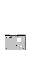
or one-meter looks like on the screen while we are creating entities. AutoCAD LT 2000 provides us with many tools to aid the construction of our designs on the screen. The Status Bar area is located at the bottom of the AutoCAD LT Drawing Screen. The words SNAP, GRID, ORTHO, POLAR, OSNAP, LWT and - Autodesk 05720-017408-9621 | Tutorial - Page 6
Geometric Construction Basics 1-5 Option Buttons GRID ON 1. Left-click the GRID button in the Status Bar to turn ON the GRID option. (Notice in the command prompt area, the message "" is also displayed.) 2. Move the cursor inside the Graphics window, and estimate the distance in between the - Autodesk 05720-017408-9621 | Tutorial - Page 7
1-6 AutoCAD® LT 2000 MultiMedia Tutorial SNAP ON 1. Left-click the SNAP button in the Status Bar to turn ON the SNAP if you haven't done so. 6. In the command prompt area, notice that "Command:" is displayed. This indicates that AutoCAD LT is waiting for us to activate the next desired command. - Autodesk 05720-017408-9621 | Tutorial - Page 8
toolbar. The icon is a picture of an eraser at the end of a pencil.) The message "Select objects" is displayed in the command prompt area and AutoCAD awaits us to select the objects to erase. 2. Left-click the SNAP button on the Status Bar to turn off the SNAP option so that - Autodesk 05720-017408-9621 | Tutorial - Page 9
1-8 AutoCAD® LT 2000 MultiMedia Tutorial 3. Move the cursor to a location that is above and toward the left side of the entities on the screen. Left-mouse- - Autodesk 05720-017408-9621 | Tutorial - Page 10
. The letter W appearing in the icon indicates that the world coordinate system (WCS) is active. The world coordinate system is a coordinate system used by AutoCAD as the basis for defining all objects and other coordinate systems. We can think of the origin of the world coordinate system as a fixed - Autodesk 05720-017408-9621 | Tutorial - Page 11
left-mouse-click will toggle the coordinate display on or off. In AutoCAD LT 2000, the absolute coordinates and the Relative coordinates can be used conjunction to the Cartesian and Polar coordinate systems. By default, AutoCAD expects us to enter values in Absolute Cartesian coordinates, distances - Autodesk 05720-017408-9621 | Tutorial - Page 12
Geometric Construction Basics 1-11 Defining Positions In AutoCAD, there are five methods to specify the locations of points moving the cursor to indicate direction and then entering a distance. The Guide Plate We will next create a mechanical design using the different coordinate entry methods. - Autodesk 05720-017408-9621 | Tutorial - Page 13
Select the LINE command icon in the Draw toolbar. In the command prompt area, near the bottom of the AutoCAD Graphics window, the message "_line Specify first point:" is displayed. AutoCAD expects us to identify the starting location of a straight line. 2. In the command prompt area, we will locate - Autodesk 05720-017408-9621 | Tutorial - Page 14
. (Notice the scroll bars can also be used to adjust viewing of the display.) 6. Press the [Esc] key to exit the PAN command. Notice that AutoCAD goes back to the LINE command. 7. We will create a vertical line by using the relative rectangular coordinates entry method, relative to the last point we - Autodesk 05720-017408-9621 | Tutorial - Page 15
1-14 AutoCAD® LT 2000 MultiMedia Tutorial Reference Coordinate System aligned at the previous point 11. Using the relative rectangular coordinates entry method to create the next line, - Autodesk 05720-017408-9621 | Tutorial - Page 16
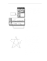
Geometric Construction Basics 1-15 Creating Circles The menus and toolbars in AutoCAD LT 2000 are designed to allow the CAD operators to quickly activate the desired commands. Besides using the Draw toolbar, we can also select the - Autodesk 05720-017408-9621 | Tutorial - Page 17
® LT 2000 MultiMedia Tutorial 2. In the command prompt area, the message "Specify center point for circle or [3P/2P/Ttr (tan tan radius)]:" is displayed. AutoCAD expects us to identify the location of a point or enter an option. We can use any of the four coordinate entry methods to identify the - Autodesk 05720-017408-9621 | Tutorial - Page 18
1-17 7. In the command prompt area, the message "Specify Diameter of circle: " is displayed. The default option for the Circle command in AutoCAD is to specify the Radius and the last radius used is also displayed in brackets. Specify Diameter of circle: 1.5 [Enter] Saving the CAD file - Autodesk 05720-017408-9621 | Tutorial - Page 19
folder to store the file. Enter GuidePlate 3. Pick SAVE in the Save Drawing As dialog box to accept the selections and save the file. Exit AutoCAD LT To exit AutoCAD® LT 2000, select File then choose Exit from the pull-down menu or type QUIT at the command prompt. - Autodesk 05720-017408-9621 | Tutorial - Page 20
How do the GRID and SNAP options assist us in sketching? 3. List and describe the different coordinate entry methods available in AutoCAD LT? 4. List and describe two types of coordinate systems commonly used for planar geometry. 5. Identify the following commands: (a) (b) (c) (d) Tan, Tan, Radius - Autodesk 05720-017408-9621 | Tutorial - Page 21
1-20 AutoCAD® LT 2000 MultiMedia Tutorial Exercises: 1. 2.
-
 1
1 -
 2
2 -
 3
3 -
 4
4 -
 5
5 -
 6
6 -
 7
7 -
8
-
9
-
10
-
11
-
12
-
13
-
14
-
15
-
16
-
17
-
18
-
19
-
20
-
21
 |
 |
WWW
.
SDC
ACAD
.
COM
±
±²³´
PUBLICATIONS
Randy H. Shih
Jack Zecher