Autodesk 05720-017408-9621 Tutorial - Page 13
Full Size, 0 [Enter], Enter, 5,0 [Enter]
 |
UPC - 606121033783
View all Autodesk 05720-017408-9621 manuals
Add to My Manuals
Save this manual to your list of manuals |
Page 13 highlights
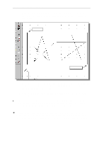
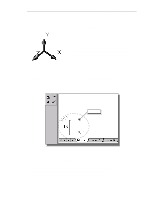
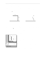
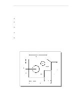
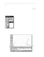
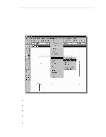
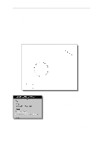
1-12 AutoCAD® LT 2000 MultiMedia Tutorial Use the ERASE command and erase all entities on the screen before proceeding to the next section. The rule for creating CAD designs and drawings is that they should be created Full Size using real-world units. The CAD database contains all the definitions of the geometric entities and the design is considered as a virtual, full-sized object. Only when a printer or plotter transfers the CAD design to paper is the design scaled to fit on a sheet. The tedious task of determining a scale factor so that the design will fit on a sheet of paper is taken care of by the CAD systems. This allows the designers and CAD operators to concentrate their attentions on the more important issues - the design. 1. Select the LINE command icon in the Draw toolbar. In the command prompt area, near the bottom of the AutoCAD Graphics window, the message "_line Specify first point:" is displayed. AutoCAD expects us to identify the starting location of a straight line. 2. In the command prompt area, we will locate the starting point of our design at the origin of the world coordinate system. Command: _line Specify first point: 0,0 [Enter] (Type 0,0 in the command prompt area and press the [Enter] key once.) 3. We will create a horizontal line by entering the absolute coordinates of the second point. Specify next point or [Undo]: 5.5,0 [Enter] (5.5,0) (0,0)
-
 1
1 -
2
-
3
-
4
-
5
-
6
-
7
-
 8
8 -
 9
9 -
 10
10 -
 11
11 -
 12
12 -
 13
13 -
 14
14 -
 15
15 -
 16
16 -
 17
17 -
 18
18 -
19
-
20
-
21
 |
 |
