Autodesk 05720-017408-9621 Tutorial - Page 14
PAN Realtime
 |
UPC - 606121033783
View all Autodesk 05720-017408-9621 manuals
Add to My Manuals
Save this manual to your list of manuals |
Page 14 highlights
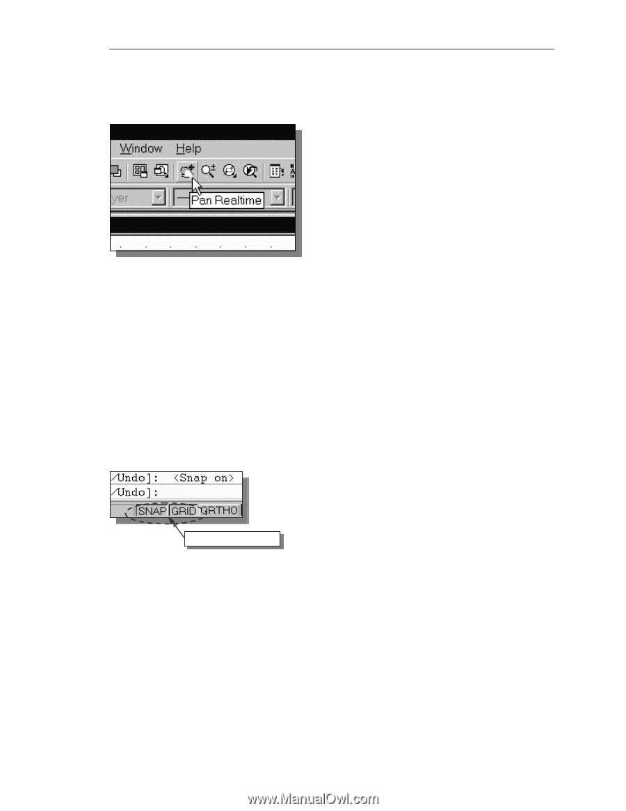
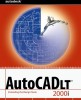
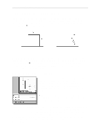
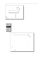
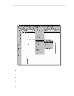
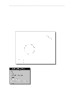
Geometric Construction Basics 1-13 The line we created is aligned to the bottom edge of the Drawing window. Let us adjust the viewing of the line by using the PAN Realtime command. 4. Click on the PAN Realtime icon in the standard toolbar area. The icon is the picture of a hand with four arrows. The PAN command enables us to move the view to a different position. This function acts as if you are using a video camera. 5. Move the cursor, which appears as a hand inside the graphics window, near the center of the drawing window, then push down the left-mouse-button and drag the display toward the right and top side until we can see the sketched line. (Notice the scroll bars can also be used to adjust viewing of the display.) 6. Press the [Esc] key to exit the PAN command. Notice that AutoCAD goes back to the LINE command. 7. We will create a vertical line by using the relative rectangular coordinates entry method, relative to the last point we specified Specify next point or [Close/Undo]: @0,2.5 [Enter] 8. We can mix any of the entry methods in positioning the locations of the endpoints. Move the cursor to the Status Bar area, and turn on the GRID and SNAP options. SNAP & GRID ON 9. Create the next line by picking the location, world coordinates (8,2.5), on the screen. 10. We will next use the relative polar coordinates entry method, relative to the last point we specified Specify next point or [Close/Undo]: @3
-
 1
1 -
2
-
3
-
4
-
5
-
6
-
7
-
8
-
 9
9 -
 10
10 -
 11
11 -
 12
12 -
 13
13 -
 14
14 -
 15
15 -
 16
16 -
 17
17 -
 18
18 -
 19
19 -
20
-
21
 |
 |