Axis Communications 240Q 240Q Blade - Installation Guide - Page 6
The I/O Terminal Block, Connector Pinout
 |
View all Axis Communications 240Q manuals
Add to My Manuals
Save this manual to your list of manuals |
Page 6 highlights
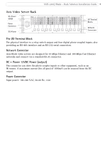
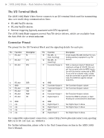
6 AXIS 240Q Blade - Rack Solution Installation Guide The I/O Terminal Block The AXIS 240Q Blade Video Server connects to an I/O terminal block used for transmitting data over multi-drop communication lines: • RS-485 Pan/Tilt devices • RS-232 Pan/Tilt devices • External triggering (typically associated with CCTV equipment) The AXIS 240Q Blade supports several Pan/Tilt device drivers, which are available from the Axis Web site at www.axis.com Connector Pinout The pinout for the I/O Terminal Block and the signaling details for each pin: Pin Function 1 RS-232 2 RS-232 3 RS-232 Description RI CTS RTS 4 RS-232 DSR 5 GND 6 RS-232 DTR 7 RS-232 TXD 8 RS-232 RXD 9 RS-232 CD 10 GND 11 n/a 12 n/a 13 n/a 14 n/a Pin Function 15 RS-485 - A (non-inverting) 16 RS-485 - B (inverting) 17 Transistor Output 4 18 GND 19 Transistor Output 3 20 Transistor Output 2 21 GND 22 Transistor Output 1 23 Digital Input 4 24 GND 25 Digital Input 3 26 Digital Input 2 27 GND 28 Digital Input 1 Description A half-duplex RS-485 interface for controlling auxiliary equipment, e.g. PTZ devices. With a maximum load of 100mA and maximum voltage of 24V DC, this output has an open-collector NPN transistor with the emitter connected to GND. To use with an external relay, a diode must be connected in parallel with the load, for protection against voltage transients. See Transistor Output 4 above. See Transistor Output 4 above. See Transistor Output 4 above. Connect to GND to activate, or leave floating (or unconnected) to deactivate See Digital Input 4 above. See Digital Input 4 above. See Digital Input 4 above. For compatible replacement connectors, contact http://www.phoenixcontact.com, quoting: MC1.5/14-ST-3.81 (art. no. 1803691). For further information, please refer to the Unit Connections section in the AXIS 240Q User's Manual.
-
 1
1 -
 2
2 -
 3
3 -
 4
4 -
 5
5 -
 6
6 -
 7
7 -
 8
8
 |
 |
